Suspension rail type rock drilling machine

The utility model relates to a rock drilling rig and a suspension rail type technology, which is applied to the suspension rail type rock drilling rig, drilling operation equipment, and rock drilling fields. , The effect of shortening operation time and low labor intensity

Active Publication Date: 2015-05-27
SHENYANG TIAN AN TECH CO LTD
View PDF11 Cites 14 Cited by
  • Summary
  • Abstract
  • Description
  • Claims
  • Application Information

AI Technical Summary

Problems solved by technology

[0006] The purpose of the present invention is to provide a suspension rail rock drilling rig, which solves the defects of the prior art that the drilling arm is not flexible enough, the movement is limited by the conditions of the roadway floor, the degree of automation is low, and the work efficiency is low. The design is reasonable and the structure is compact. It takes up little space in the roadway, easy to operate, stable in movement, safe and reliable. While ensuring the required working space in the roadway, it can perform permanent support operations such as bolts and anchor cables according to different geological conditions and roadway section shapes, and It can realize the drilling operation in the blasting face, which can significantly improve the production efficiency and support quality of the tunneling face

Method used


Image

  • Suspension rail type rock drilling machine
  • Suspension rail type rock drilling machine
  • Suspension rail type rock drilling machine

Examples


Embodiment Construction

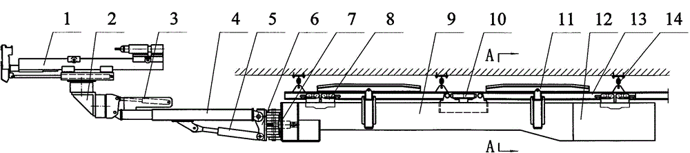
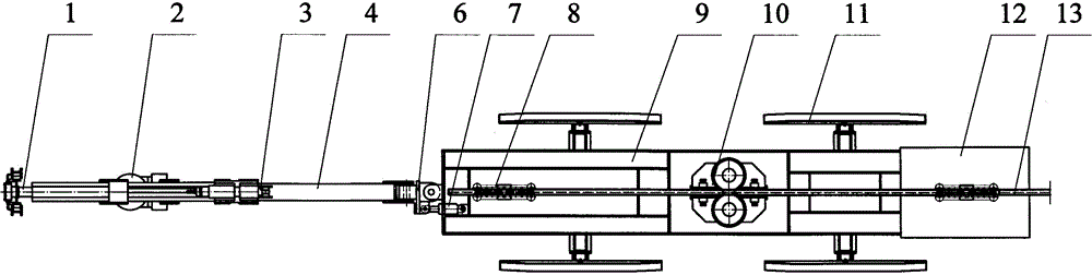
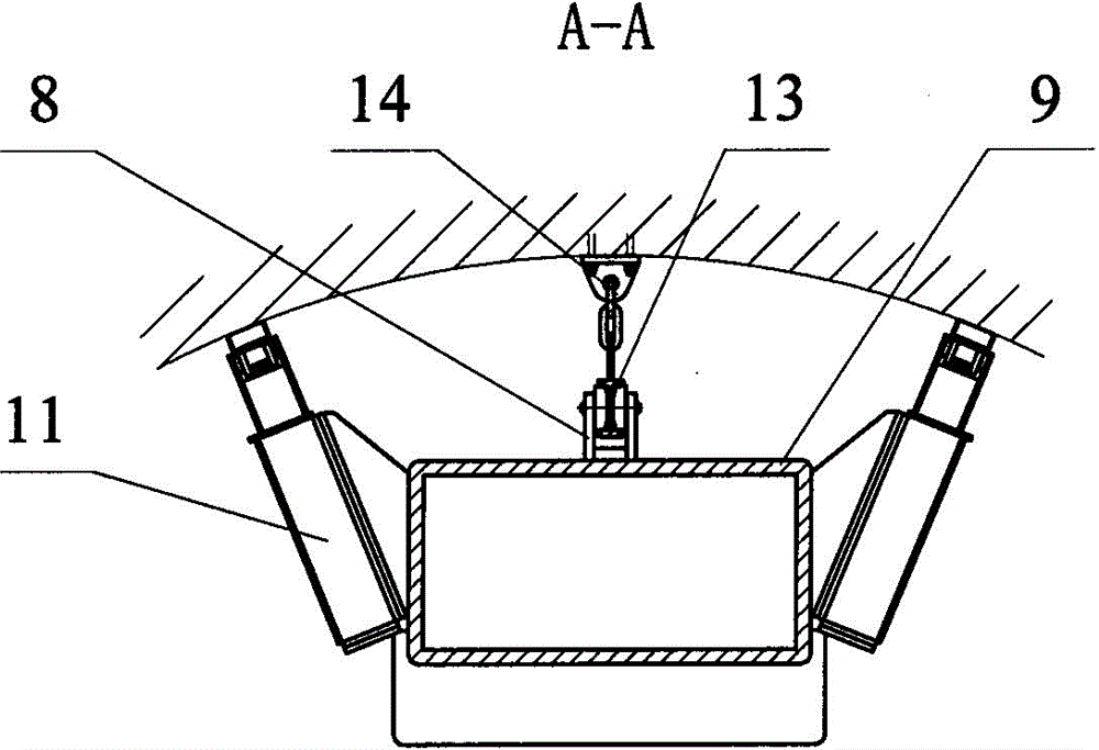
[0021] according to Figure 1-9 The specific structure of the present invention will be described in detail. The suspension rail rock drilling rig can be made into type I according to the actual use requirements (such as Figure 1~2 shown) structure or type II (such as Figure 8-9 shown) structure. It includes body 9, rock drilling device 1, running gear and hydraulic pump station 12 etc. parts. Taking the type I structure as an example, the body 9 is assembled on the traveling track 13 through the driving wheel 10 and the driven wheel 8 of the traveling mechanism, and the driven traveling wheel 8 and the driving wheel 10 that support and walk along the traveling track 13 are fixed by brackets On airframe 9. In order to facilitate braking and positioning during operation, a braking device (not shown in the drawings) is provided on the driving wheel 10 . Walking track 13 utilizes hanging fastener 14 to hang on the roadway top, and walking track 13 can adopt single track or...


PUM


Abstract

The invention provides a suspension rail type rock drilling machine which can be used for solving the defects of poor flexibility of a drilling arm, movement restriction due to a tunnel bottom plate condition, low degree of automation, low working efficiency and the like in the prior art. The suspension rail type rock drilling machine comprises a machine body, a rock drilling device, a travelling mechanism and a hydraulic pump station and is technically characterized in that a rectangular-axis slewing mechanism and a rock drilling device control arm which is provided with a vertical-regulation hydraulic cylinder, a lifting hydraulic cylinder and a transverse-regulation hydraulic cylinder are adopted for connecting the rock drilling device; a driven travelling wheel and a driving wheel on the upper part of the machine body are adopted for moving along a travelling rail at the top of a tunnel; the hydraulic pump station which is suspended on the travelling rail by use of the driven travelling wheel is connected to the rear part of the machine body. The suspension rail type rock drilling machine is reasonable in design, compact in structure, small in tunnel occupied space, simple and convenient to operate, and stable, safe and reliable in movement, can perform permanent support operations such as anchor rod drilling and anchor rope drilling according to different geological conditions and the cross-section shape of the tunnel and can perform blasting hole drilling operation on a blasting working face, so that the production efficiency and support quality of a driving working face are remarkably improved.

Description

technical field [0001] The present invention relates to a kind of rock drilling and drilling operation equipment used for anchor installation, water exploration, gas exploration and rock breaking in tunnel and roadway excavation engineering, especially a method that adopts suspension self-moving walking mode to cooperate with the excavation process suspended rail rock drilling rig. Mainly used in engineering, coal mine, metal mine, chemical industry, railway, hydropower and other industries. The utility model belongs to the technical field of rock roadway excavation machinery and bolter drilling rigs. Background technique [0002] At present, in rock drilling and drilling operations in engineering tunnels and mine roadways where shield equipment cannot be used, the traditional method is to use artificial pneumatic or hydraulic drilling rigs for rock drilling operations. This method requires operators to hold the drilling rig in the dangerous area. Operation, and the drilli...

Claims


Application Information

Patent Timeline
Patent Type & Authority Applications(China)
IPC IPC(8): E21B7/02E21B15/00E21B1/00E21D20/00E21D9/10
CPCE21B7/02E21B7/027E21B15/00E21D20/003
Inventor 曹伟邱洋高永强华志坚王皓王荣亮
Owner SHENYANG TIAN AN TECH CO LTD
Why Eureka
Try Eureka