Kiln tail and bypath wind releasing residual heat boiler of cement kiln

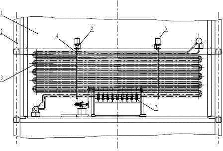
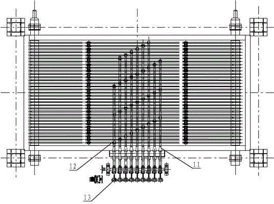
A technology for bypass ventilation and waste heat boiler, applied in boiler water pipes, steam boilers, steam boiler accessories, etc., can solve the problems of reducing the heat transfer efficiency of boiler heat transfer surface tubes, reducing the thermal efficiency of waste heat boilers, and increasing secondary energy consumption. Achieve the effect of avoiding the reduction of heat exchange efficiency, reducing the air leakage of the system, and good vibration transmission effect

Active Publication Date: 2015-05-27
JIANGSU DONGJIU HEAVY IND
View PDF6 Cites 2 Cited by
  • Summary
  • Abstract
  • Description
  • Claims
  • Application Information

AI Technical Summary

Problems solved by technology

The waste heat flue gas contains a large amount of dust. When the flue gas passes through the waste heat boiler for heat exchange, it will adhere to the surface of the heat transfer surface tube of the boiler to varying degrees to hinder heat transfer and reduce the thermal efficiency of the waste heat boiler; at the same time, the flue gas is in the waste heat boiler. The resistance along the flow increases, thereby additionally increasing secondary energy consumption
[0004] At present, most of the waste heat boilers at the kiln tail of the cement kiln and the bypass ventilation adopt vertical boilers, and the heat transfer surface tubes of the vertical boilers are arranged horizontally and horizontally. It will reduce the heat transfer efficiency of the boiler heat transfer surface tube

Method used


Image

  • Kiln tail and bypath wind releasing residual heat boiler of cement kiln
  • Kiln tail and bypath wind releasing residual heat boiler of cement kiln
  • Kiln tail and bypath wind releasing residual heat boiler of cement kiln

Examples


Embodiment Construction

[0029] The present invention will be further explained below in conjunction with the accompanying drawings and specific embodiments. It should be understood that the following specific embodiments are only used to illustrate the present invention but not to limit the scope of the present invention. It should be noted that these drawings are all simplified schematic diagrams, and only schematically illustrate the basic structure of the present invention, so they only show the configurations related to the present invention.

[0030] In describing the present invention, it should be understood that the terms "center", "longitudinal", "transverse", "upper", "lower", "front", "rear", "left", "right", " The orientations or positional relationships indicated by "vertical", "horizontal", "top", "bottom", "inner" and "outer" are based on the orientations or positional relationships shown in the drawings, and are only for the convenience of describing the present invention and Simplif...


PUM


Abstract

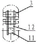
The invention discloses a kiln tail and bypath wind releasing residual heat boiler of a cement kiln. The kiln tail and bypath wind releasing residual heat boiler comprises a boiler body which has a vertical structure, heat transferring surface pipes arranged in a flue of the boiler body, and a vibration ash removing device matched with the heat transferring surface pipes, wherein the heat transferring surface pipes are arranged in the flue of the boiler body in a vertical arrangement manner; each heat transferring surface pipe is vertically and integrally arranged; the vibration ash removing device is arranged at the bottoms of the vertical directions of the heat transferring surface pipes or close to the bottoms of the vertical directions of the heat transferring surface pipes. According to the kiln tail and bypath wind releasing residual heat boiler, when ash is cleaned by vibration, the heat transferring surface pipes are used as a whole body to carry out ash cleaning operation, the vibration transferring effect is good, and the ash cleaning effect is remarkable; deposited ash sequentially falls off from top to bottom so that the ash is prevented from being deposited on the surfaces of the heat transferring surface pipes, and a phenomenon that the heat exchanging efficiency of the heat transferring surface pipes is reduced can be effectively avoided.

Description

technical field [0001] The invention relates to the field of pure medium and low temperature waste heat recovery of cement clinker production line, and more specifically relates to a waste heat boiler for cement kiln kiln tail and bypass ventilation. Background technique [0002] Cement enterprises are large energy consumers in the production of the national economy, and the cement industry has been listed as one of the key areas of resource conservation in the country. Under the background of the State Council's policy of accelerating the construction of a conservation-oriented society, it is of great significance to improve the conservation-oriented manufacturing and application level of the cement industry and establish a conservation-oriented cement industry system. In the current situation where the contradiction between energy supply and demand is prominent at home and abroad, energy saving and consumption reduction has become a subject that must be completed in the ce...

Claims


Application Information

Patent Timeline
Patent Type & Authority Applications(China)
IPC IPC(8): F22B1/18F22B37/10F22B37/20F23J3/00F27D17/00
CPCY02P10/25
Inventor 林仟国程立春杨玉慧
Owner JIANGSU DONGJIU HEAVY IND
Why Eureka
Try Eureka