WGGH (Water Gas Gas Heater) system

A No. 1, FGR technology, applied in the WGGH system field, can solve the problems of no energy saving, equipment waste, and low utilization rate, and achieve the effects of ensuring safety and no corrosion, huge economic benefits, and improving unit efficiency

Active Publication Date: 2015-05-27
DONGFANG BOILER GROUP OF DONGFANG ELECTRIC CORP
View PDF6 Cites 2 Cited by
  • Summary
  • Abstract
  • Description
  • Claims
  • Application Information

AI Technical Summary

Problems solved by technology

[0010]However, the WGGH system has excessive energy consumption in application, low utilization rate, and basically no energy-saving effect. Specifically, the WGGH system has the following deficiencies Where:
[0011]1. FGC lowers the flue gas temperature from 150-160°C to 90-95°C, while FGR raises the temperature of the desulfurized net flue gas from 50°C to 80°C ℃; so the heat absorbed and released by the heat medium water in its internal circulation are not equal; at this time, if there is no corresponding temperature adjustment equipment in the system, the heat medium water will appear after several cycles of heat medium water. The temperature deviates from the design temperature. Under the condition that the heat exchange area of ​​the FGC and FGR heat exchangers is constant, the flue gas temperature at the outlet of the cooling section and the heating section will also deviate from the design temperature, which cannot achieve the original design effect, thus affecting the dust removal efficiency and desulfurization cannot be guaranteed. After net flue gas heating effect, causing chimney corrosion
[0012]2. The existing WGGH system is equipped with an auxiliary steam source, which is used in the initial stage of system startup and when the load is low. Discharge system, at this time, the water temperature of the condensed water in the discharge system is about 110-120°C, direct discharge will lose this part of heat
[0013]3. When the water temperature in the heat medium water internal circulation reaches a constant requirement, the water entering the FGR from the FGC still has to pass through the auxiliary steam heater at full flow to increase the system resistance , resulting in waste of equipment and waste of resources

Method used


Image

  • WGGH (Water Gas Gas Heater) system
  • WGGH (Water Gas Gas Heater) system
  • WGGH (Water Gas Gas Heater) system

Examples


Embodiment

[0037] One, the arrangement of WGGH of the present invention:

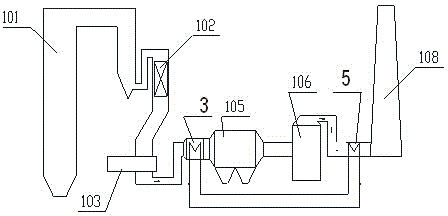
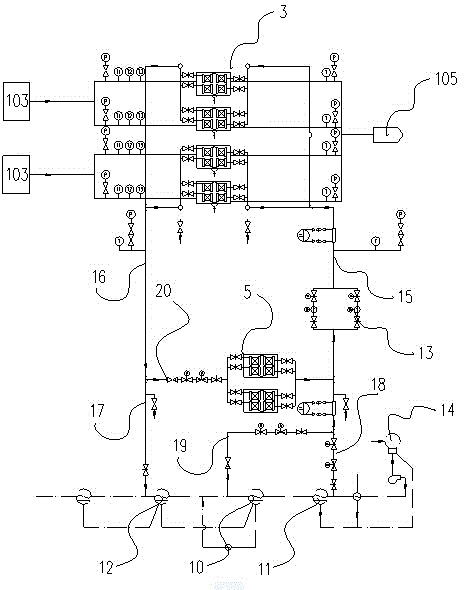
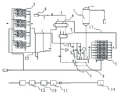
[0038] Such as image 3 As shown, the WGGH system of the present invention includes FGC3, FGR5, two-point water intake circuit 19, return water circuit 17, circulating booster pump 13 and condensate water pipeline. FGC3 is connected to the rear end of the air preheater 103, the temperature of the flue gas coming out of the air preheater 103 is about 130 degrees, and the temperature required by the dust collector 105 behind the FGC3 is about 95 degrees, therefore, here, the FGC3 needs to put the flue gas that enters into it The flue gas temperature is reduced from about 130 degrees to about 95 degrees, and the corresponding flue gas temperature from the desulfurization tower in front of FGR5 is about 50 degrees, and the flue gas temperature required by the chimney is about 80 degrees. Therefore, FGR needs to enter The flue gas temperature in it rises from about 50 degrees to about 80 degrees. For this reason, F...


PUM


Abstract

The invention discloses a WGGH (Water Gas Gas Heater) system. The system comprises an FGC (Flue Gas Cooler), an FGR (Flue Gas Reheater), a two-point water taking loop and a condensate pipe, wherein one water taking point of the two-point water taking loop is connected to the condensate pipe in front of an eighth low pressure heater, and another water taking point of the two-point water taking loop is connected to the condensate pipe between a sixth low pressure heater and a seventh low pressure heater; the pipeline after water taking of the two-point water taking loop is connected to a first main loop through a main water taking loop. By using a two-point condensate feeding mode, a water return pipeline is additionally arranged to control the mixing temperature after the two-point water taking and guarantee that a heated surface of a heat exchanger is not corroded and the temperature of heat medium water and gas does not deviate from a design value; the environmental protection requirement of zero emission can be guaranteed through the WGGH system; the WGGH system is used as a temperature adjusting system indispensable for super clean emission, so great economic benefit is brought.

Description

technical field [0001] The invention relates to a WGGH system, in particular to a WGGH system involving a new water intake pipeline, which belongs to the technical field of boiler systems. Background technique [0002] Before the appearance of WGGH (water gas heater heat medium water-gas-gas heat exchanger), the boiler process is: the flue gas from the furnace passes through the SCR reactor and then enters the air preheater, and then the flue gas from the air preheater After entering the dust collector, the flue gas after dust removal by the dust collector enters the desulfurization tower, and the flue gas desulfurized by the desulfurization tower is discharged to the atmosphere through the chimney. [0003] Since the temperature of the dust collector is required to be about 95 degrees, and the temperature of the flue gas from the air preheater is about 135 degrees, a separate heat collector is set between the two to cool down, and this section is called the cooling sectio...

Claims


Application Information

Patent Timeline
Patent Type & Authority Applications(China)
IPC IPC(8): F23J15/06F23J15/08
CPCY02E20/30
Inventor 陈刚易兵李红兵
Owner DONGFANG BOILER GROUP OF DONGFANG ELECTRIC CORP
Why Eureka
Try Eureka