Modularization corrugated plate type heat exchanger

A corrugated plate heat exchanger technology, applied in the direction of heat exchanger type, heat exchanger shell, indirect heat exchanger, etc., can solve the problems of complex structure and process, heavy weight, low flue gas discharge temperature, etc., and reach the later stage The operation and maintenance are simple and convenient, the number of heat exchange fins is reduced, and the effect of good heat exchange recovery efficiency

Inactive Publication Date: 2016-11-16
刘启端
View PDF7 Cites 4 Cited by
  • Summary
  • Abstract
  • Description
  • Claims
  • Application Information

AI Technical Summary

Problems solved by technology

[0002] Existing heat exchangers used in exhaust gas and waste heat recovery have the following disadvantages: 1. The discharge flow rate of the flue gas is much larger than the flow rate of the combustion-supporting gas for heat exchange with it, and it is difficult for the system to digest the heat in the flue gas to the maximum extent, resulting in There is still a lot of waste heat in the flue gas that is wasted; in addition, when the flue gas is subjected to water mist dust removal, desulfurization and denitrification environmental protection treatment, a lower flue gas discharge temperature is required, and the flue gas still carries a large...

Method used


Image

  • Modularization corrugated plate type heat exchanger
  • Modularization corrugated plate type heat exchanger
  • Modularization corrugated plate type heat exchanger

Examples


Embodiment Construction

[0022] The specific embodiments of the present invention are described below so that those skilled in the art can understand the present invention, but it should be clear that the present invention is not limited to the scope of the specific embodiments. For those of ordinary skill in the art, as long as various changes Within the spirit and scope of the present invention defined and determined by the appended claims, these changes are obvious, and all inventions and creations using the concept of the present invention are included in the protection list.

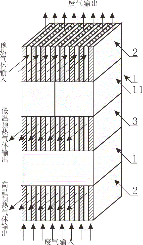
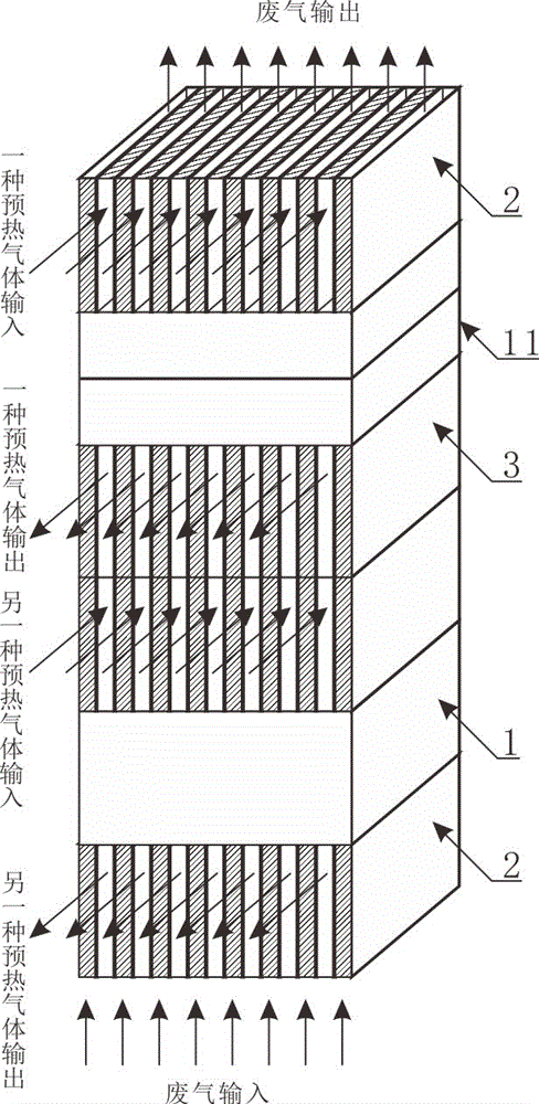
[0023] Such as figure 1 with figure 2 As shown, the modular corrugated plate heat exchanger includes a heat exchange assembly 1, two end flow guide modules 2 and at least one middle flow guide module 3, and the heat exchange assembly 1 is composed of at least one heat exchange module 11 connected in series or in parallel.

[0024] Due to the unique setting of the positions of the heat exchange component 1, the end guide m...


PUM


Abstract

The invention discloses a modularization corrugated plate type heat exchanger which comprises end flow guide modules, middle flow guide modules and heat exchange assemblies. Each heat exchange assembly is formed by connecting one or more heat exchange modules in series or in parallel. Each heat exchange module comprises a heat exchange shell and wave-shaped heat exchange fins. Each heat exchange shell is of a rectangle structure with the upper end face and the lower end face being opened. The wave-shaped heat exchange fins are overlapped together and fixed into the heat exchange shells. Each end flow guide module comprises a flow guide box with three continuous faces arranged to be opened. A plurality of L-shaped channel baffles are fixedly arranged in the flow guide boxes, and short arms of the adjacent channel baffles are vertically distributed in the inside space of the flow guide boxes. Each middle flow guide module comprises a flow guide shell with three continuous faces arranged to be opened; plate-shaped baffles and L-shaped air flow baffles are arranged in the flow guide shells at intervals; and the plate-shaped baffles make contact with the L-shaped air flow baffles. At least one middle flow guide module is arranged between every two adjacent heat exchange assemblies, and each end flow guide module is mounted at the free end of the corresponding heat exchange assembly.

Description

technical field [0001] The invention belongs to the field of waste gas waste heat recovery equipment, and in particular relates to a modular corrugated plate heat exchanger for energy exchange between combustion boilers, industrial furnace waste gas and combustion-supporting gas. Background technique [0002] Existing heat exchangers used in exhaust gas and waste heat recovery have the following disadvantages: 1. The discharge flow rate of the flue gas is much larger than the flow rate of the combustion-supporting gas for heat exchange with it, and it is difficult for the system to digest the heat in the flue gas to the maximum extent, resulting in There is still a lot of waste heat in the flue gas that is wasted; in addition, when the flue gas is subjected to water mist dust removal, desulfurization and denitrification environmental protection treatment, a lower flue gas discharge temperature is required, and the flue gas still carries a large amount of waste heat, making it...

Claims


Application Information

Patent Timeline
IPC IPC(8): F23L15/00F28D9/00F28F9/22
CPCF23L15/00F28D9/0037F28F9/22F28F2009/222Y02E20/34
Inventor 刘启端
Owner 刘启端
Why Eureka
Try Eureka