Single signal arrival angle estimating method based on large-scale multi-antenna system

A multi-antenna system, angle of arrival technology, applied in directions such as direction finders using radio waves, can solve problems such as a large number of sampling samples, reduced estimation accuracy, and inapplicability to large-scale multi-antenna systems, to improve spectrum utilization, reduce The effect of pilot overhead

Active Publication Date: 2015-05-27
武汉优博汇泰信息技术有限责任公司
View PDF2 Cites 6 Cited by
  • Summary
  • Abstract
  • Description
  • Claims
  • Application Information

AI Technical Summary

Problems solved by technology

In the ESPRIT algorithm, the estimation of signal-related parameters is obtained through rotation invariance between two identical subspaces, but it requires a larg

Method used


Image

  • Single signal arrival angle estimating method based on large-scale multi-antenna system
  • Single signal arrival angle estimating method based on large-scale multi-antenna system
  • Single signal arrival angle estimating method based on large-scale multi-antenna system

Examples


Embodiment 1

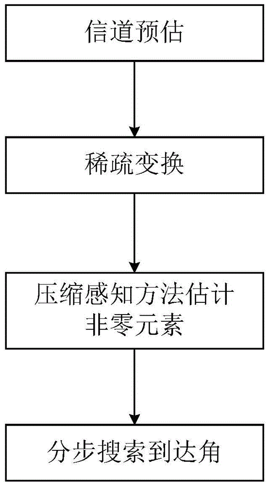
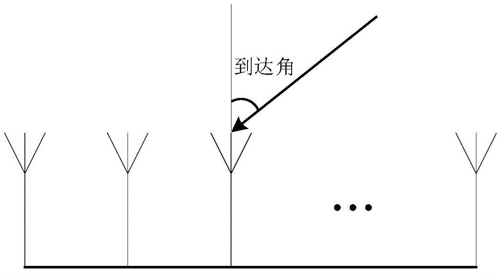
[0030] figure 2 Shown is a schematic diagram of a linear antenna array model in Embodiment 1 of the present invention, and the single signal angle of arrival estimation method based on a large-scale multi-antenna system of the present invention is used in a large-scale multi-antenna system in which the receiving antenna array is a linear antenna array, specifically Include the following steps:

[0031] Step 1 In the linear antenna array of the embodiment of the present invention, a single angle of arrival is 60 degrees, and the receiving antenna array is a linear array composed of 16 antennas. According to the characteristics of the unitary matrix, the estimated value of the channel matrix in the time domain can be obtained by simple matrix multiplication in For the conjugate transposition of the transmitted signal matrix X, Y=HX+N is the received signal matrix;

[0032] Step 2 The prediction matrix itself does not have the sparse characteristic, so construct the sparse ...

Embodiment 2

[0037] Figure 4 Shown is a schematic diagram of a planar antenna array model in Embodiment 2 of the present invention. The difference between Embodiment 2 and Embodiment 1 is that this embodiment uses the method for estimating the angle of arrival of a single signal based on a large-scale multi-antenna system in the present invention. In a large-scale multi-antenna system where the receiving antenna is a planar antenna array, the following steps are specifically included:

[0038] Step 1 In the planar antenna array of the embodiment of the present invention, 16 receiving antennas are distributed as a 4×4 planar array, and the channel matrix is ​​estimated

[0039] Step 2 The prediction matrix itself does not have the sparse characteristic, so construct the sparse transformation matrix Φ according to the correlation between the receiving antennas in the large-scale multi-antenna system, and perform sparse transformation on the prediction matrix A sparse matrix G with a spa...


PUM


Abstract

The invention discloses a single signal arrival angle estimating method based on a large-scale multi-antenna system and belongs to the technical field of processing of signals in large-scale multi-antenna system channel estimation. The method comprises the following steps: (1) pre-estimating a channel matrix; (2) constructing a sparse transformation matrix by utilizing the correlation among receiving antennas and performing sparse transformation on a channel estimated value matrix to obtain a matrix with sparse properties; (3) accurately estimating nonzero elements in the sparse matrix according to a compressive perception principle; (4) estimating a signal arrival angle by adopting step-by-step searching. According to the single signal arrival angle estimating method, a signal arrival angle estimated value can be obtained only through a signal sample, the precision is high, and the spectrum utilization ratio can be improved. Through the step-by-step searching, the searching precision is improved, the signal arrival angle estimation precision is improved, and the estimation complexity is reduced. Through higher practicability, the single signal arrival angle estimating method can be applied to the estimation of various system parameters with sparse properties.

Description

technical field [0001] The invention belongs to the technical field of signal processing for channel estimation of a large-scale multi-antenna system, and more particularly relates to a method for estimating the angle of arrival of a single signal based on a large-scale multi-antenna system. Background technique [0002] The angle at which the target signal is incident on the receiving antenna array is called the angle of arrival. The target azimuth parameter can be obtained by estimating the angle of arrival, which is a very critical part of channel estimation, and it is also a research hotspot in recent years. [0003] In the early estimation of the angle of arrival of array signals, the beamforming algorithm is a representative algorithm, but this algorithm has certain limitations. Only when the reciprocal of the array aperture is smaller than the source distance can the azimuth of the signal source be compared. valid estimate. In the 1980s, a subspace signal angle-of-a...

Claims


Application Information

Patent Timeline
IPC IPC(8): G01S3/02
CPCG01S3/02
Inventor 彭薇江涛魏肖
Owner 武汉优博汇泰信息技术有限责任公司
Why Eureka
Try Eureka