The control circuit that the braking energy of the motor is supplied to the DC load in real time

A DC load and motor braking technology, applied in the field of circuits, can solve the problems of large volume, high cost, slow investment recovery, etc., and achieve the effects of good energy saving, high utilization efficiency and high reliability.

Active Publication Date: 2017-04-19
重庆三木华瑞机电有限公司
View PDF4 Cites 0 Cited by
  • Summary
  • Abstract
  • Description
  • Claims
  • Application Information

AI Technical Summary

Problems solved by technology

The shortcomings of the existing schemes are: 1. Although the energy consumption method is the most commonly used method for small and medium-sized motor systems at present, all the braking energy is consumed on the heat loss of the braking resistor; 2. Although the feedback method can reduce large Part of the braking energy of the motor is fed back to the power grid to achieve energy saving, but the additional active inverter device is large in size and high in investment. In the small and medium-capacity motor system, the investment recovery is slow; The rated voltage is not high, and the voltage on the DC bus side is generally high, so the supercapacitor bank device combined in series and parallel is bulky, high in cost, and has limited energy storage

Method used


Image

  • The control circuit that the braking energy of the motor is supplied to the DC load in real time
  • The control circuit that the braking energy of the motor is supplied to the DC load in real time

Examples


Embodiment Construction

[0010] The present invention will be further described below in conjunction with accompanying drawing.

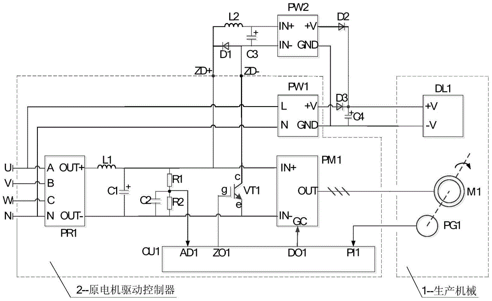
[0011] Such as figure 1 As shown, the motor braking energy is supplied to the control circuit of the DC load in real time, including the motor main control circuit and the braking energy DC / DC dispatching circuit.

[0012] The motor main control circuit includes rectifier module PR1, power module PM1, AC / DC module PW1, motor controller CU1, DC load DL1, motor M1, encoder PG1, brake tube VT1, rectifier inductor L1, rectifier capacitor C1, detection capacitor C2, the upper voltage divider resistor R1, the lower voltage divider resistor R2, the A-phase input terminal A of the rectifier module PR1 is connected to the A-phase terminal U terminal of the power supply, the live wire terminal L terminal of the AC / DC module PW1, and the B-phase of the rectifier module PR1 The input terminal B is connected to the B-phase terminal V of the power supply, the C-phase input terminal C of...


PUM


Abstract

The invention relates to a control circuit for real-time supply of motor braking energy to a DC load, including a motor main control circuit, a braking energy DC / DC dispatching circuit, specifically including a rectifier module PR1, a power module PM1, an AC / DC module PW1, a DC / DC DC module PW2, freewheeling diode D1, upper strobe diode D2, lower strobe diode D3, motor controller CU1, DC load DL1, motor M1, encoder PG1, brake tube VT1, rectifier inductor L1, buffer inductor L2, Rectifier capacitor C1, detection capacitor C2, buffer capacitor C3, output capacitor C4, upper voltage divider resistor R1, lower voltage divider resistor R2, etc. The invention automatically converts the braking energy of the motor to such DC loads after DC / DC conversion. The braking energy of the motor in the invention has high conversion and utilization efficiency, good energy saving effect, low cost, convenient application and high reliability. .

Description

technical field [0001] The invention belongs to the field of industrial control and relates to a circuit, in particular to a control circuit for supplying motor braking energy to DC loads in real time, which is suitable for electromechanical equipment containing DC loads and can supply motor braking energy in real time DC loads to achieve energy-saving control occasions. Background technique [0002] In the production electromechanical equipment driven by motors, in order to achieve rapid deceleration or stop control of production machinery, it is necessary to quickly transfer the braking energy of the motor from the shaft. In the motor drive control system based on the power electronic speed control device, the commonly used braking energy processing schemes are: first, the energy consumption method, through real-time monitoring of the DC bus voltage in the speed control device and combined with the system operation command, when When it is judged that the motor is braking...

Claims


Application Information

Patent Timeline
Patent Type & Authority Patents(China)
IPC IPC(8): H02P3/00H02M3/00
Inventor 陈德传陈雪亭
Owner 重庆三木华瑞机电有限公司
Why Eureka
Try Eureka