

Full hardware signal light coding circuit
A coding circuit and signal light technology, applied in the direction of pulse duration/width modulation, etc., can solve the problems of high production cost and high software management cost, and achieve the effect of low production cost, eliminating software management and convenient adjustment.
- Summary
- Abstract
- Description
- Claims
- Application Information
AI Technical Summary
Problems solved by technology
Method used
Image

Examples
Embodiment Construction
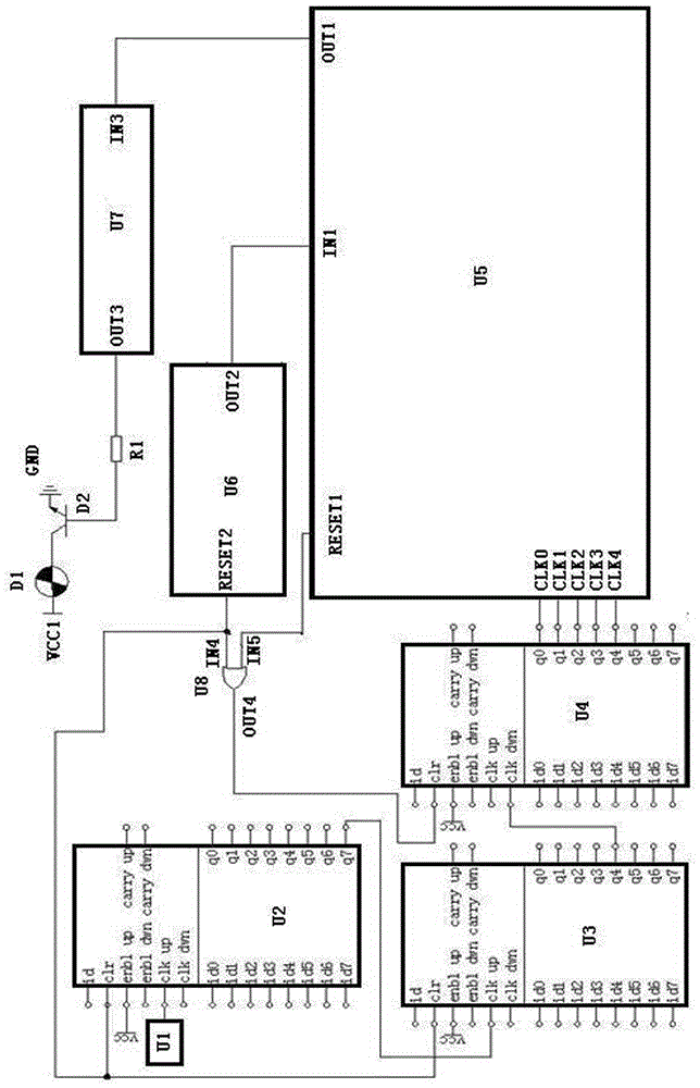
[0041] The specific implementation, features and functions of the all-hardware signal light encoding circuit according to the present invention will be described in detail below in conjunction with the accompanying drawings and preferred embodiments.
[0042] An all-hardware signal light encoding circuit of the present invention consists of a crystal oscillator U1, an 8-bit counter U2, an 8-bit counter U3, an 8-bit counter U4, a logic control circuit U5, a mode control circuit U6, a pulse width control circuit U7, a dual-input single Output AND gate U8, resistor R1, signal light D1, NPN transistor D2, power supply VCC, signal light power VCC1, signal light power ground GND;
[0043] The output terminal of the crystal oscillator U1 is connected to the input terminal CLK UP of the 8-bit counter U2, the output terminal Q7 of the 8-bit counter U2 is connected to the input terminal CLK UP of the 8-bit counter U3, and the output terminal Q4 of the 8-bit counter U3 is connected to the...
PUM
 Abstract
Description
Claims
Application Information