Slurry removal groove

A technology of desliming tank and tank body, which is applied in the field of desliming tank, which can solve the problems of unfavorable pulp particle dispersion, small disturbance, and poor desliming effect, so as to improve the flow and distribution state, reduce the number of equipment, and increase production capacity. big effect

Active Publication Date: 2015-06-03
ZHONGYE-CHANGTIAN INT ENG CO LTD
View PDF10 Cites 2 Cited by
  • Summary
  • Abstract
  • Description
  • Claims
  • Application Information

AI Technical Summary

Problems solved by technology

Its disadvantage is that when the pulp moves in the equipment, the disturbance is small, which is not conducive to the dispersion of particles in the pulp, especially when it is used in the selective flocculation and desliming process of selectively adsorbing and flocculating useful mineral particles to remove gangue slime. Useful minerals will entrain a large amount of gangue mud that should have been discharged from the overflow and sink, resulting in poor desliming effect

Method used


Image

  • Slurry removal groove
  • Slurry removal groove

Examples


Embodiment Construction

[0031] In order to enable those skilled in the art to better understand the solution of the present invention, the present invention will be further described in detail below in conjunction with the accompanying drawings and specific embodiments.

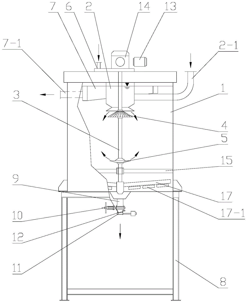
[0032] Please refer to figure 1 , figure 1 It is a structural schematic diagram of a specific embodiment of the desilting tank provided by the present invention.

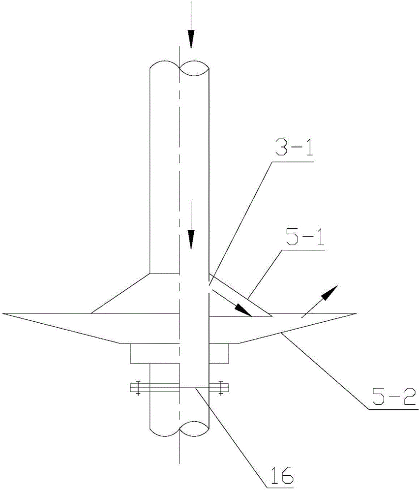
[0033] In a specific embodiment, the desilting tank provided by the present invention is mainly composed of a tank body 1, a material receiving cylinder 2, a central shaft 3, a distribution plate 4, a flushing water plate 5, a water supply device 6, an overflow tank 7 and a frame 8 and other components, wherein the material receiving cylinder 2 and the distribution plate 4 constitute the slurry distribution system, the central shaft 3 and the flushing water plate 5 constitute the flushing water system, and the whole machine composed of the above components is supported o...


PUM


Abstract

The invention discloses a slurry removal groove. The slurry removal groove comprises a groove body (1), a material receiving cylinder (2), a central shaft (3), a distributor disc (4), a rinse water disc (5), a water supply device (6) and an overflow groove (7), wherein a slurry valve is arranged on an ore discharge pipe (9) at the bottom of the groove body (1), a feed pipe (2-1) is arranged on the material receiving cylinder (2), the central shaft (3) is arranged along the axial central line of the groove body (1), a drive device which drives the groove body (1) to rotate is arranged on the groove body (1), the distributor disc (4) is installed on the central shaft (3) and located below a discharge port at the bottom of the material receiving cylinder (2), the rinse water disc (5) is installed on the central shaft (3) and located on the middle lower area of the groove body (1), a water injection nozzle is arranged on the rinse water disc (5), the water supply device (6) is communicated with the water injection nozzle of the rinse water disc (5) through a channel in the central shaft (3), and an overflow pipe (7-1) is arranged on the overflow groove (7). The slurry removal groove is high in slurry removal and concentration efficiency, and large in production capacity per unit area, and can achieve use effects of two segments or even multiple segments of slurry removal and concentration.

Description

technical field [0001] The invention relates to the technical field of mineral processing equipment, in particular to a desliming tank used for desliming treatment of ore pulp. Background technique [0002] Desliming and thickening are common operations in the beneficiation production process. The basic principle is to use the ore (or ore aggregate) to settle out of the slurry by its own gravity to achieve the purpose of desliming or dehydration. [0003] At present, conventional desliming and thickening equipment mainly include desliming buckets, thickeners, inclined plate thickeners, etc. [0004] The desliming hopper is also widely used in small and medium-sized mineral processing plants in my country. It is mainly used to deslim and concentrate the feed material before sorting and grading operations, and it also plays a buffer role. However, due to its low concentration and desliming efficiency and small equipment specifications, it is gradually being replaced by thicke...

Claims


Application Information

Patent Timeline
Patent Type & Authority Applications(China)
IPC IPC(8): B03B5/66
Inventor 张田肖业俭吴革雄刘相佩刘克俭
Owner ZHONGYE-CHANGTIAN INT ENG CO LTD
Why Eureka
Try Eureka