A method of pickling and purging hydraulic pipelines

A hydraulic pipeline and pickling technology, which is applied to cleaning methods and appliances, chemical instruments and methods, and cleaning hollow objects, etc., can solve the problems of inconvenience, pipeline pollution, increasing installation flanges and unions, etc. The method is feasible and the cost is low The effect of low and shortened construction period

Active Publication Date: 2016-08-17
MCC5 GROUP CORP SHANGHAI
View PDF5 Cites 0 Cited by
  • Summary
  • Abstract
  • Description
  • Claims
  • Application Information

AI Technical Summary

Problems solved by technology

The disadvantage of the second construction method is that the size of the pickling tank should be considered in the section of the pipeline, and a large number of installation flanges and unions should be added. At the same time, the pipeline after pickling and purging is easily polluted when it is installed again
[0003] Therefore there are above-mentioned inconveniences and problems in the known hydraulic pickling and purging construction method

Method used


Image

  • A method of pickling and purging hydraulic pipelines
  • A method of pickling and purging hydraulic pipelines

Examples


Embodiment 1

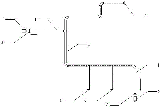
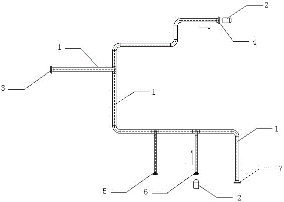
[0040] The pickling and purging method for hydraulic pipelines of the present invention is characterized in that it comprises the following steps:

[0041] a. Tank-type pickling of hydraulic pipelines, including the following steps:

[0042] (1) Carry out tank pickling and passivation of hydraulic pipelines;

[0043] (2) After pickling and passivation, dry the water in the pipe with compressed air;

[0044] (3) After the pipe is blown, apply 20# weather anti-rust oil;

[0045] (4) Seal the nozzles at both ends of the oil-coated pipeline with sealing tape;

[0046] (5) When the nominal diameter of the pipeline is less than DN50, the pipeline is filled with some nitrogen gas when sealing the second nozzle, and the degree of nitrogen filling is qualified if the flame of the lighter can be extinguished when the nozzle is opened.

[0047] b. Pipeline installation, including the following steps:

[0048] (1) Pay attention to the dust in the installation environment during pipeli...

Embodiment 2

[0064] The nominal diameter of the pipeline is less than DN50 and the pipeline is purged

[0065] 1) First use abrasive grain type A to clean the head, dip some acetone on the cleaning head when purging;

[0066] 2) After purging, check that there are no large particles on the surface of the cleaning head at the outlet end, and then use the joint type C cleaning head to purge;

[0067] 3) Inspection: The surface color of the imported and exported cleaning head has not changed much; no tiny particles can be seen with the naked eye; the inner wall of the purged pipeline can see metallic luster, which is qualified;

[0068] 4) The number of cleaning heads used for pipeline purging is generally 5 for one pipeline.

[0069] The rest of this embodiment is the same as embodiment 1.

Embodiment 3

[0071] Nominal diameter of pipe > DN50 pipe purging

[0072] 1) The blasting membrane for blasting and purging is made of high-pressure cardboard with a thickness of 2mm, and the initiation pressure is controlled at 0.3Mpa according to the size of the pipe diameter;

[0073] 2) Set a firm target plate and protective measures at the purge port, and the target plate is made of 20mm thick wood.

[0074] The rest of this embodiment is the same as embodiment 1.


PUM

PropertyMeasurementUnit
thicknessaaaaaaaaaa

Abstract

An acid pickling blowing method of a hydraulic pipeline is characterized by comprising the following steps of a, tank type acid pickling of the hydraulic pipeline, b, mounting of the pipeline, and c, using a pneumatic pipeline cleaning system for online blowing of the pipeline. The acid pickling blowing method of the hydraulic pipeline has the advantages that the method is advanced in process, feasible in method, safe, easy and convenient to operate and capable of visually checking the acid pickling quality of the interior and the exterior of the pipeline; the acid pickling and oil flushing working periods are shortened, and the acid pickling quality can be ensured; and compared with online acid picking, the cost is lower, and the economic benefits are better.

Description

technical field [0001] The invention relates to a pipeline pickling and purging method, in particular to a hydraulic pipeline pickling and purging method. Background technique [0002] There are two traditional hydraulic pickling and purging construction methods: the first one is after the pipeline installation is completed, online pickling and then blowing with compressed air, that is, online cycle pickling, which is to use temporary pipelines (hose or hard pipes) for the system pipelines. Pipes) are connected to form a loop, and the acid pump is used to drive the acid liquid into the pipeline for cyclic pickling. In the first construction method, the installed pipeline does not need to be disassembled, only the hydraulic components are disconnected and connected with hoses or hard pipes. The disadvantage of the first construction method is that it is difficult to achieve turbulent flow due to the limitation of pickling equipment flow, pressure and pipeline system installa...

Claims


Application Information

Patent Timeline
Patent Type & Authority Patents(China)
IPC IPC(8): B08B9/027B08B9/032
CPCC23G3/04F26B21/00
Inventor 饶邦林黄文虎
Owner MCC5 GROUP CORP SHANGHAI
Why Eureka
Try Eureka