Intensive pre-treatment equipment for city and town restaurant-kitchen wastes

A technology for kitchen waste and pretreatment, applied in the direction of solid waste removal, etc., can solve the problem of no urban kitchen waste classification collection, transportation and treatment device, etc., to achieve reduction and comprehensive utilization, and reduce investment costs. , the effect of simplifying the processing process

Inactive Publication Date: 2015-06-03
黑龙江中科瑞合环保技术服务有限公司
View PDF6 Cites 7 Cited by
  • Summary
  • Abstract
  • Description
  • Claims
  • Application Information

AI Technical Summary

Problems solved by technology

[0004] The present invention solves the problem that the existing kitchen wastes are all concentrated in large-scale large-scale cities, and there is no device for t

Method used


Image

  • Intensive pre-treatment equipment for city and town restaurant-kitchen wastes

Examples


specific Embodiment approach 1

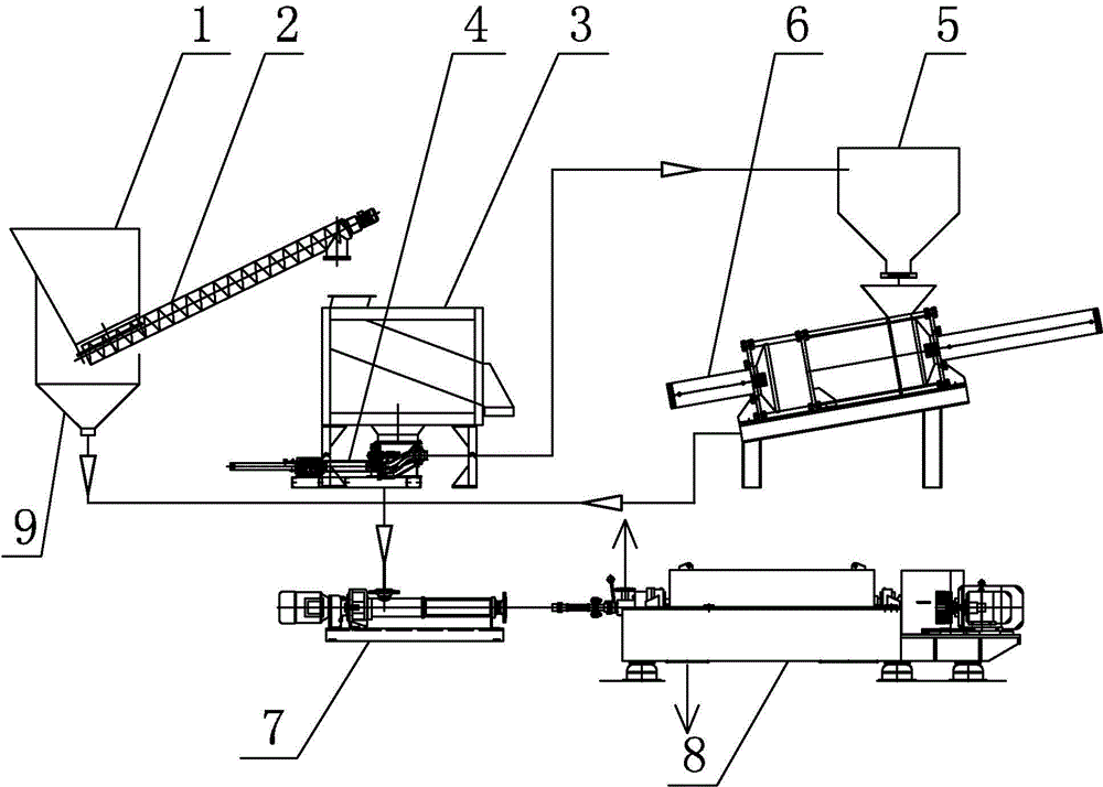
[0012] Specific implementation manner one: such as figure 1 As shown, the urban kitchen waste intensive pretreatment equipment of this embodiment includes a hopper 1, a drain screw conveyor 2, a sorter 3, a piston pump 4, a buffer silo 5, a press 6, and a leachate transfer pump 7. The three-phase separator 8 and the filtrate collection hopper 9, the lower end of the collection hopper 1 and the inlet of the drain screw conveyor 2 are connected with each other. The drain screw conveyor 2 is arranged at an inclined angle, and the inlet of the drain screw conveyor 2 is lower than The discharge port of the drain screw conveyor 2 has a drain hole at the bottom of the inlet end of the drain screw conveyor 2, and the diameter of the drain hole is 4-6mm. A filtrate collection bucket 9 is arranged below the inlet end of the drain screw conveyor 2, and the drain The discharge port of the screw conveyor 2 is located directly opposite to the upper inlet of the sorter 3. The lower end of the...

specific Embodiment approach 2

[0015] Specific implementation manner two: such as figure 1 As shown, the drain screw conveyor 2 in this embodiment is a dual-frequency drain screw conveyor. With such a design, the conveying capacity can be adjusted according to the load of the downstream equipment, and at the same time, it can be reversed to prevent the drain screw conveyor 2 from being blocked. The other components and connection relationships are the same as in the first embodiment.

specific Embodiment approach 3

[0016] Specific implementation manner three: such as figure 1 As shown, the hole diameter of the drain hole in this embodiment is 5 mm. It is convenient for the water to flow out from the drain hole, and the materials to be placed flow out from the drain hole. Other components and connection relationships are the same as those in the first or second embodiment.


PUM

PropertyMeasurementUnit
Lengthaaaaaaaaaa
Particle sizeaaaaaaaaaa

Abstract

The invention provides intensive pre-treatment equipment for city and town restaurant-kitchen wastes, relates to waste pre-treatment equipment, and aims at solving the problems that existing city and town restaurant-kitchen wastes are intensively treated in cities in a large scale, and no specialized city and town restaurant-kitchen waste classified collection, transportation, and treatment device exists. The lower end of a material collection hopper is communicated with a feeding hole of a water leaching spiral conveyor; a feeding hole of the water leaching spiral conveyor is lower than a discharging hole of the water leaching spiral conveyor; a water leaching hole is formed in the bottom of the water leaching spiral conveyor; a filtrate collection hopper is arranged under the inlet end of the water leaching spiral conveyor; the discharging hole of the water leaching spiral conveyor is formed in a manner of being opposite to an inlet in the upper part of a sorting machine; the lower end of the sorting machine is communicated with an inlet of a piston pump; an outlet of the piston pump is communicated with the upper part of a buffering stock bin; the lower end of the buffering stock bin is communicated with a feeding hole of a squeezer; and the lower part of the filtrate collection hopper and a liquid-phase outlet of the squeezer are communicated with an inlet of a three-phase separator by a percolate conveying pump. The intensive pre-treatment equipment can be used for intensive treatment of the city and town restaurant-kitchen wastes.

Description

Technical field [0001] The invention relates to an intensive pretreatment equipment for urban kitchen waste, belonging to the technical field of kitchen waste treatment. Background technique [0002] At present, the treatment of food and kitchen waste in my country is in its infancy. The food wastes are all large-scale centralized treatments in large cities. There are problems such as high investment, large area, and complicated processing equipment; small and medium-sized cities and towns are classified into food and kitchen waste. Transportation and processing are in urgent need of development, and it is not suitable for the construction of large-scale restaurant and kitchen waste treatment facilities. The population is small and the amount of restaurant waste generation is low. At the same time, it is necessary to consider issues such as investment and construction land. Therefore, the development and promotion of biotechnology systems and supporting equipment that are suitable...

Claims


Application Information

Patent Timeline
IPC IPC(8): B09B3/00B09B5/00
Inventor 徐诚蛟胡国峰石淼张毅方石洪影孙秋君王亮
Owner 黑龙江中科瑞合环保技术服务有限公司
Why Eureka
Try Eureka