Cutting machine with double oblique draw bars

A technology of oblique pull rod and cutting machine, which is applied in the direction of metal sawing equipment, metal processing machinery parts, maintenance and safety accessories, etc. Many problems, such as the large area occupied by the inner pressure plate and the outer pressure plate, achieve the effect of light weight, stable tension and simple structure

Active Publication Date: 2015-06-03
ZHEJIANG JINGSHEN IND
View PDF8 Cites 2 Cited by
  • Summary
  • Abstract
  • Description
  • Claims
  • Application Information

AI Technical Summary

Problems solved by technology

[0007] The present invention aims at the following disadvantages in the prior art double-slant rod type cutting machine: one is that the saw blade positioning and clamping device includes an inner pressure plate and an outer pressure plate, and the saw blade is arranged and clamped between the inner pressure plate and the outer pressure plate, but the inner The surfaces of the pressure plate and the outer pressure plate are flat, and the saw blade is only clamped on the flat surface of the inner pressure plate and the outer pressure plate, which makes the positioning and clamping effect poor, and the area occupied by the inner pressure plate and the outer pressure plate is large, making The output shafts passing through the inner pressure plate and the outer pressure plate are also longer, so that the width of the protective cover outside the saw blade is also larger, resulting in larger consumables and higher cost; second, the protective device generally adopts a fixed protective cover or a fixed The protective plate also has a movable protective cover or a movable protective plate installed on the fixed protective cover or the fixed protective plate, but the main problem of the above-mentioned protective device is: on the one hand, the protective range of the fixed protective cover or the fixed protective plate is limited, and the cutting device When cutting, the movable protection cannot follow the movement of the cutting device; on the other hand, there is a movable protective cover or movable protective plate on the existing fixed protective cover. The movable protective cover or the movable protective plate is not coaxial with the fixed protective cover or the fixed protective plate. The central setting makes the movable protective cover or movable protective plate more consumables and heavier in weight and higher in cost; the third is that the driving device adopts a gear box, and the gear box body is generally made of a metal box, which is heavy, has poor ventilation and heat dissipation performance, and The cost is high, and the gear box is generally used to drive the motor of the gear box, which makes the installation of the motor and the gear box as the driving device inconvenient and takes up too much space, which affects the overall installation and work of the cutting machine; the fourth is the pulley transmission device The belt pulley transmission device is adopted, and the belt generally adopts a belt with six annular grooves. The main problems of the belt with six annular grooves are: first, the friction between the belt and the pulley is large when the 2400W belt saw works at high speed, so that the belt, pulley It is easy to wear and has a short service life, and it is even prone to belt scorching due to excessive friction of the belt; second, the belt width of the six annular grooves is relatively large, which makes the belt less elastic, the tension force is not stable enough, and the assembly is difficult. It is time-consuming and labor-intensive; thirdly, there are more belt consumables in the six annular grooves, which makes the cost higher; in addition, there are also problems that the sliding cross bar is easy to fall after sliding to the maximum position, and the rear frame and crank arm are heavy and unload the machine head. Poor cushioning effect, serious waste of materials in the assembly structure of the base and extension rods, resulting in high costs, etc., provides a kind of internal pressure plate and external pressure plate for snap-in positioning and clamping, and the fixed protective cover and the movable protective cover are coaxial Setting, the front box and the rear box are covered, and the rear box is connected with the motor casing to form a gearbox, and the gearbox and the motor casing are made of plastic, with less consumables, lighter weight and lower cost. cutting machine

Method used


Image

  • Cutting machine with double oblique draw bars
  • Cutting machine with double oblique draw bars
  • Cutting machine with double oblique draw bars

Examples


Embodiment 1

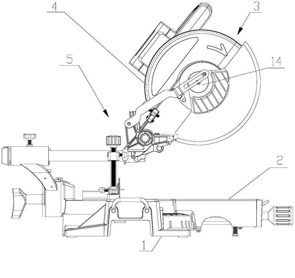
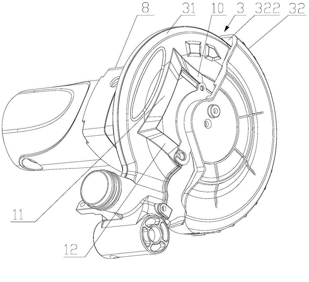
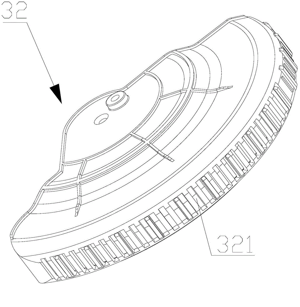
[0047] A kind of double oblique rod type cutting machine, such as Figure 1-18 As shown, including a base 1, a workbench 2, a rotating mechanism 5, and a saw blade 4, the workbench 2 and the rotating mechanism 5 are all arranged on the base 1, the saw blade 4 is supported on the rotating mechanism 5, and the saw blade 4 is provided with Protection device 3, saw blade 4 both sides are provided with positioning clamping device, and protection device 3 comprises fixed protective cover 31 and the movable protective cover 32 that is hinged outside fixed protective cover 31, and positioning clamping device comprises inner pressure plate 6 and is arranged inside. The outer pressure plate 7 on the pressure plate 6, the saw blade 4 is sandwiched between the inner pressure plate 6 and the outer pressure plate 7, the saw blade 4 is connected with a driving device through a pulley transmission, the driving device includes a gear box 8, and the pulley transmission includes a belt 9, Belt 9...


PUM

PropertyMeasurementUnit
thicknessaaaaaaaaaa
thicknessaaaaaaaaaa
thicknessaaaaaaaaaa

Abstract

The invention relates to a cutting machine, and discloses a cutting machine with double oblique draw bars. The cutting machine comprises a base, a worktable, a rotary mechanism and a saw blade. A semicircular movable protective cover is arranged on the outside of the saw blade, an inner pressure plate and an outer pressure plate are arranged on two sides of the saw blade, the saw blade is sandwiched between the inner pressure plate and the outer pressure plate and is connected with a plastic gear box by a belt pulley transmission gear, the belt pulley transmission gear comprises a four-groove belt, and the inner pressure plate is clamped and embedded on the outer pressure plate. The cutting machine has the advantages that the saw blade can be positioned and clamped by a clamping and embedding type positioning and clamping device, accordingly, minor-axis sections can be shortened to the greatest extent, and a protective device can be narrowed to the greatest extent; the semicircular movable protective cover which is coaxially arranged is hinged onto a fixed protective cover, can move along with a cutting device and has a movable protective function; a front tank and a rear tank can be closed, and the rear tank is integrally connected with a motor shell, so that the gear box can be formed; the gear box and the motor shell are made of plastics, and accordingly the cutting machine is low in material consumption and cost and is light.

Description

technical field [0001] The invention relates to a cutting machine, in particular to a double oblique stay rod cutting machine. Background technique [0002] At present, cutting machines are widely used in the cutting and processing of various workpieces, and have made great progress. Existing cutting machines generally include a base, a workbench and a rotating mechanism arranged on the base, a saw blade supported and connected to the rotating mechanism for cutting workpieces, a pulley transmission for driving the saw blade to rotate, and a driving pulley transmission. The driving device can complete the cutting tasks of some profiles or workpieces to a certain extent, but the following problems generally exist: [0003] One is that the saw blade positioning and clamping device includes an inner pressure plate and an outer pressure plate. The saw blade is set between the inner pressure plate and the outer pressure plate and is clamped, but the surfaces of the inner pressure...

Claims


Application Information

Patent Timeline
Patent Type & Authority Applications(China)
IPC IPC(8): B23D47/00B23D47/12B23D47/02B23D59/00B23Q11/06B23Q11/08
Inventor 叶伟豪
Owner ZHEJIANG JINGSHEN IND
Why Eureka
Try Eureka