Linear drive pumping unit

A linear drive, pumping unit technology, applied in the direction of electromechanical devices, electric components, control mechanical energy, etc., can solve the problems of unreachable, increased operating costs, pipe and rod fatigue, etc., to achieve easy transportation and installation, low transportation and installation costs, The effect of improving performance

Active Publication Date: 2017-03-01
华运隆腾机械制造有限公司
View PDF5 Cites 0 Cited by
  • Summary
  • Abstract
  • Description
  • Claims
  • Application Information

AI Technical Summary

Problems solved by technology

[0004] Major oilfields in China have entered the mid-to-late stage of development, the formation pressure has decreased, and the liquid supply capacity is insufficient. Even when the swabbing parameters of the beam pumping unit have been adjusted to the minimum, the coordination of supply and production cannot be achieved. In addition, the upstream beam pumping The structural design of the pump itself determines that the power of the equipped motor is relatively large, and the phenomenon of "big horse-drawn carts" is common in the operation of the pumping unit, which not only wastes a lot of electric energy, but also causes serious phenomena such as air pumping of the oil pump when the liquid supply is insufficient, and the liquid serious shock phenomenon, serious wear of oil well pumps, fatigue operation of pipe rods, shortened service life, and increased operating costs. On the premise of ensuring crude oil production, in order to reduce energy consumption, reduce investment, and improve economic benefits, oilfield exploitation urgently needs a light-load and high-efficiency pump Energy-saving extraction equipment

Method used


Image

  • Linear drive pumping unit
  • Linear drive pumping unit

Examples


Embodiment Construction

[0015] The present invention will be further described below in conjunction with accompanying drawing:

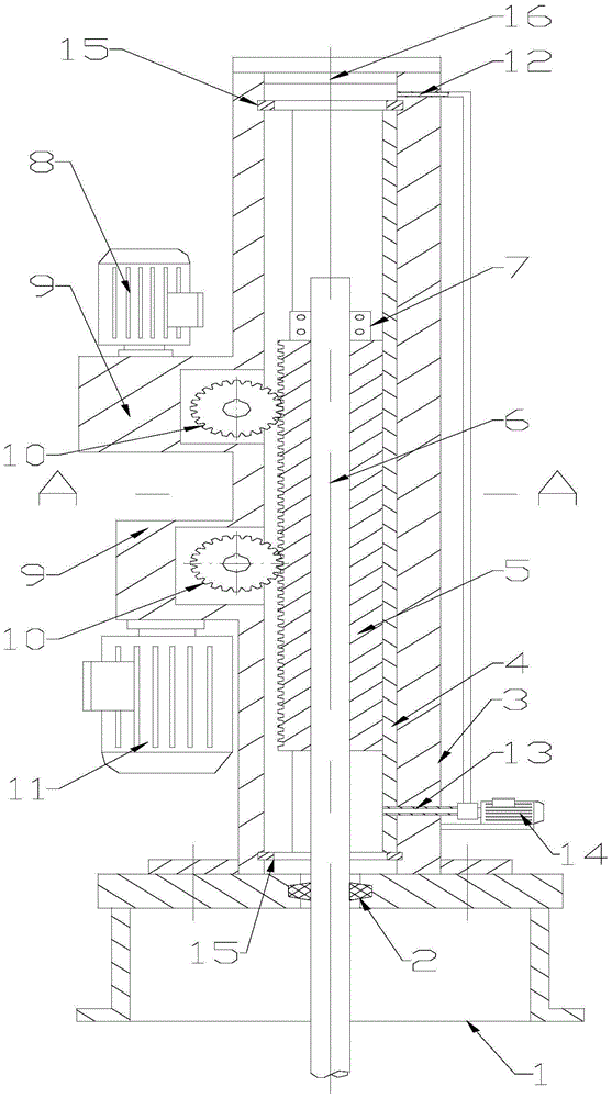
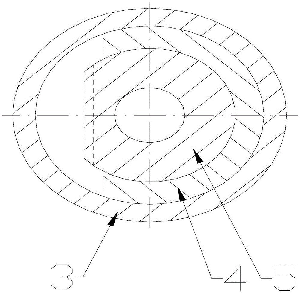
[0016] Depend on figure 1 combine figure 2 As shown, the linear drive pumping unit includes a base 1, the upper end of the base 1 is sealed with a flange connected to the pipe string 3, and the transition fit in the pipe string 3 is connected to the guide sleeve 4. The transition fit makes the guide sleeve 4 unable to rotate in the pipe string 3, ensuring that The opening position of the guide sleeve 4 faces the teeth of the rack 5, and the upper and lower ends of the guide sleeve 4 are provided with retaining rings 15 for holes to be fixedly connected with the pipe column 3 to fix the guide sleeve 4. The guide sleeve 4 is an opening where the solid part of the pipe exceeds a semicircle A section of cylinder, the inner hole of the guide sleeve 4 is matched with the outer cylindrical surface of the rack 5, the position of the opening side of the guide sleeve 4, the side of...


PUM


Abstract

The invention provides a linear driving oil pumping unit. The inside of a pipe string at the upper end of a base is in transitional fit connection with a guide sleeve; an inner hole of the guide sleeve is connected with a rack in a matched manner; involute teeth are formed on one side of the rack; the upper part of the involute teeth of the rack is meshed with a gear, and another gear at the lower part is meshed with the involute teeth of the rack; the upperpart of the gear is connected with a generator, and the lower part of the gear is connected with a motor; an inner hole of the rack is in clearance fit with an oil pumping rod; the upper part of the oil pumping rod extends out of the rack part and is fixedly connected with an oil pumping rod clamping hoop; the lower part of the oil pumping rod extends out of the lower end of the pipe column and the lower end of a base. By fit of the generator and the motor, the potential energy caused by descending of the oil pumping rod is effectively absorbed to generate power, so that the descending potential energy of the oil pumping rod can be used to the maximum extent, the efficiency is improved, and power is saved; by the linear driving oil pumping unit with low-inertia design, higher efficiency can be achieved, transportation and mounting are facilitated, and the transportation and mounting costs are low; when the linear driving oil pumping unit replaces an existing discharging and mining oil pumping unit, under-well work is not needed, direct replacement can be realized, and convenience and quickness can be achieved.

Description

[0001] Technical field: [0002] The invention relates to the field of petroleum production equipment, in particular to a linear drive pumping unit. [0003] Background technique: [0004] Major oilfields in China have entered the mid-to-late stage of development, the formation pressure has decreased, and the liquid supply capacity is insufficient. Even when the swabbing parameters of the beam pumping unit have been adjusted to the minimum, the coordination of supply and production cannot be achieved. In addition, the upstream beam pumping The structural design of the pump itself determines that the power of the equipped motor is relatively large, and the phenomenon of "big horse-drawn carts" is common in the operation of the pumping unit, which not only wastes a lot of electric energy, but also causes serious phenomena such as air pumping of the oil pump when the liquid supply is insufficient, and the liquid serious shock phenomenon, serious wear of oil well pumps, fatigue ope...

Claims


Application Information

Patent Timeline
Patent Type & Authority Patents(China)
IPC IPC(8): E21B43/00
CPCE21B43/126H02K7/116
Inventor 徐海英
Owner 华运隆腾机械制造有限公司
Why Eureka
Try Eureka