Magnetorheological fluid load simulator and design method of structure parameter of load simulator

A load simulator, magnetorheological fluid technology, applied in the testing of machine/structural components, instruments, measuring devices, etc., can solve the problems of increasing the damping torque, reducing the sealing performance of the sealing ring, increasing the damping torque of zero magnetic field, etc.

Active Publication Date: 2015-06-03
CHONGQING UNIV
View PDF4 Cites 7 Cited by
  • Summary
  • Abstract
  • Description
  • Claims
  • Application Information

AI Technical Summary

Problems solved by technology

[0005] This application simulates three basic loads: constant power, constant torque, and fan load by providing a magnetorheological fluid load simulator and its structural parameter design method, and uses the combination of the magnetic conduction ring and the magnetic isolation ring to form a curve Shaped magnetic flux path increases the damping torque without increasing the volume of

Method used


Image

  • Magnetorheological fluid load simulator and design method of structure parameter of load simulator
  • Magnetorheological fluid load simulator and design method of structure parameter of load simulator
  • Magnetorheological fluid load simulator and design method of structure parameter of load simulator

Examples


Embodiment 1

[0052] The load simulator designed by the present invention needs to simulate three basic loads: constant torque, constant power, and fan load, so the present invention selects a rotary load simulator structure, and the rotary load simulator can be divided into a disc type and a circular load simulator. There are two types of cylinders. Since the excitation coil of the disc load simulator is set on the outer cylinder body, its radial dimension is increased, so it has a larger radial dimension, while the cylinder load simulator sets the excitation coil inside the damper , making it more compact. In the case of the same damping torque output, the cylindrical rotating load simulator is more compact, so the present invention will adopt the rotating cylindrical magnetorheological fluid load simulator, which is a load simulator based on the shearing working mode .

[0053] Such as figure 1 As shown, a rotating cylinder magneto-rheological fluid load simulator includes a cylinder ...

Embodiment 2

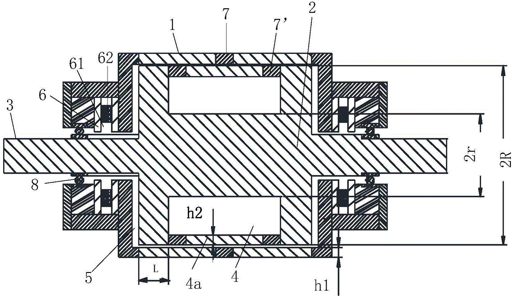
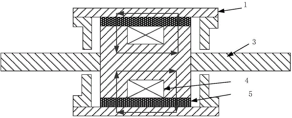
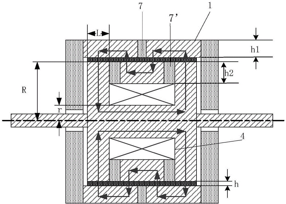
[0106] Such as figure 1 As shown, a rotating cylinder magneto-rheological fluid load simulator includes a cylinder 1, a damping cylinder 2 arranged inside the cylinder 1, a transmission shaft 3 connected to the damping cylinder 2, and a The excitation coil 4 made on the damping cylinder 2, the transmission shaft 3 protrudes from both ends of the cylinder 1 respectively, and fills the working gap between the cylinder 1 and the damping cylinder 2 There is a magneto-rheological fluid 5 , and a sealing mechanism 6 for sealing the magnetorheological fluid 5 is provided at both ends of the cylinder 1 . The sealing mechanism 6 is a sealing sleeve, the inner wall of the sealing sleeve is provided with an annular groove 61, and an annular magnet 62 is set in the groove, and the working gap between the sealing sleeve and the transmission shaft 3 is filled with Magnetorheological fluid5.

[0107]Further, a bearing mechanism 8 for installing the transmission shaft 3 is provided outside ...


PUM

PropertyMeasurementUnit
Magnetic inductionaaaaaaaaaa

Abstract

The invention provides a magnetorheological fluid load simulator and a design method of a structure parameter of the load simulator. The load simulator simulates three basic loads: constant power, constant torque and a ventilator load, and comprises a cylinder barrel, a damping drum, a shaft, an excitation coil and a magnetorheological fluid. A curved flux path is formed by combining a magnetic conducting ring and a magnetic isolation ring, so that damping moment is increased without increasing the size of the load simulator; a self-sealing technology of the magnetorheological fluid solves the technical problems that zero magnetic field damping moment of the load simulator is increased due to sealing of the magnetorheological fluid with an O-shaped sealing ring and the sealability is reduced due to excessive wear of the sealing ring caused by long-time operation in the prior art; and the load simulator is simple in structure and good in sealability.

Description

technical field [0001] The invention relates to a load simulator, in particular to a magneto-rheological fluid load simulator and a design method for its structural parameters. Background technique [0002] The load simulator is a semi-physical simulation device that simulates the air damping moment of the aircraft during flight under laboratory conditions. It is mainly used to implement damping loading on the steering gear system of new missiles, launch vehicles and other aircraft. It is a typical torque servo control system. During the simulation experiment, the air damping torque is simulated and the steering gear system is loaded in real time. The steering gear system bears the damping torque applied by the load simulator system when the angular displacement servo control is performed. According to the different roles of the two in the simulation test, the load simulator system is called the loading system, and the steering gear system is called the bearing system. The...

Claims


Application Information

Patent Timeline
IPC IPC(8): G01M99/00
Inventor 叶兆虹孙跃苏玉刚戴欣王智慧唐春森
Owner CHONGQING UNIV
Why Eureka
Try Eureka