A design method for shaft distribution and operation optimization in landfill

A landfill and design method technology, applied in the direction of calculation, special data processing applications, instruments, etc., can solve the problems of inability to obtain collection efficiency, achieve the effect of improving biogas collection efficiency, increasing economic benefits, and avoiding delays in construction

Active Publication Date: 2017-04-05
INST OF ROCK & SOIL MECHANICS CHINESE ACAD OF SCI
View PDF2 Cites 0 Cited by
  • Summary
  • Abstract
  • Description
  • Claims
  • Application Information

AI Technical Summary

Problems solved by technology

[0004] The present invention solves the problem that the shaft design scheme in the prior art fails to provide a reasonable optimization method for the overall layout of the shafts in the landfill by providing a method for optimizing the distribution and operation of the shafts in the landfill. In the case of large differences in biogas output in landfills, the technical problem of not being able to obtain ideal collection efficiency has achieved a reasonable optimization of the overall layout of the shafts of the landfill. Ideal collection efficiency can be obtained when there are large differences in biogas output patterns in different landfills in different regions

Method used


Image

  • A design method for shaft distribution and operation optimization in landfill
  • A design method for shaft distribution and operation optimization in landfill
  • A design method for shaft distribution and operation optimization in landfill

Examples


Embodiment Construction

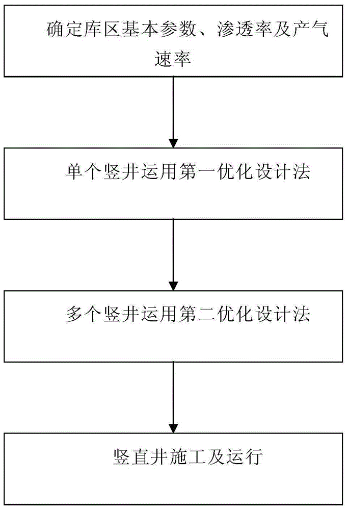
[0027] See attached figure 1 , a method for optimizing the design of shaft distribution and operation for landfills provided by the embodiment of the present application, comprising the following steps:

[0028] S1: Determine the basic parameters of the reservoir area where the shaft is located.

[0029] S2: Measure the permeability and gas production rate of the garbage dump in the reservoir area.

[0030] S3: According to the basic parameters, permeability and gas production rate, use the first optimal design method to calculate the gas pressure value of a single shaft, and at the same time, calculate the individual gas pressure values ​​corresponding to different pumping intensities, perforation section lengths and permeability Describe the flow value of the shaft and establish a flow database.

[0031] S4: According to the flow database, use the second optimal design method to determine the optimal well spacing, perforating section length and gas extraction intensity of ...


PUM


Abstract

The invention discloses a vertical shaft distribution and operation optimization design method for a garbage landfill. The vertical shaft distribution and operation optimization design method for the garbage landfill comprises the following steps of determining basic parameters of a reservoir area in which vertical shafts are located; determining the permeability and biogas production rate of a garbage pile in the reservoir area; calculating flow values of a single vertical shaft corresponding to different biogas extraction strength, holed section length and permeability by using a first optimization design method; determining the optimum shaft spacing, holed section length and biogas extraction strength of a plurality of vertical shafts by using a second optimization design method according to a flow database; performing vertical shaft construction and operating the plurality of vertical shafts according to the optimum biogas extraction strength. The method targets at the maximization of the vertical shaft collection capacity, the prediction of the collection capacity of the plurality of vertical shafts is carried out, the optimized scheme for collaborative operation of the plurality of vertical shafts is given, the control and collection of biogas in the reservoir area of the landfill are enhanced by optimizing the distribution and operation state of the biogas extraction shafts, the collection efficiency of a collection system is effectively improved and a technical support is provided for improving the operation efficiency of a landfill biogas power generation project.

Description

technical field [0001] The invention relates to the technical field of pollution prevention and control of landfill sites, in particular to a method for optimizing the design of shaft distribution and operation for landfill sites. Background technique [0002] Gas collection systems in landfills can generally be divided into two categories: horizontal gas pipe collection systems and vertical shaft collection systems. At present, most of the gas well collection systems of domestic waste landfills operated and developed are based on the "Technical Specifications for Domestic Garbage Sanitary Landfill" (CJJ17-2004), which stipulates that shafts (pipes) should be used for landfill gas guidance facilities, and shafts (pipes) can also be used. Horizontal pipe (ditch) or guiding facilities connected horizontally and vertically. It is stipulated in the setting of the vertical shaft that the vertical shaft can use a perforated gabion in the center, and the outside of the perforated ...

Claims


Application Information

Patent Timeline
Patent Type & Authority Patents(China)
IPC IPC(8): G06F19/00
Inventor 刘磊薛强曾刚王平陈亿军马骏
Owner INST OF ROCK & SOIL MECHANICS CHINESE ACAD OF SCI
Why Eureka
Try Eureka