Eureka AIR delivers breakthrough ideas for toughest innovation challenges, trusted by R&D personnel around the world.

Methanol Fuel Cell Anode Flow Field Plate

A methanol fuel cell and anode flow field technology, which is applied to fuel cells, battery electrodes, circuits, etc., can solve the problems of large volume and low fuel utilization rate, and achieve the effects of high structural strength, improved fuel utilization rate, and less damage.

Inactive Publication Date: 2017-10-10
ZHONGBEI UNIV
View PDF2 Cites 0 Cited by
  • Summary
  • Abstract
  • Description
  • Claims
  • Application Information

AI Technical Summary

Problems solved by technology

[0004] In order to solve the problems of low fuel utilization rate and large volume of existing methanol fuel cells, the present invention provides a methanol fuel cell anode flow field plate

Method used


Image

  • Methanol Fuel Cell Anode Flow Field Plate

Examples


Embodiment 1

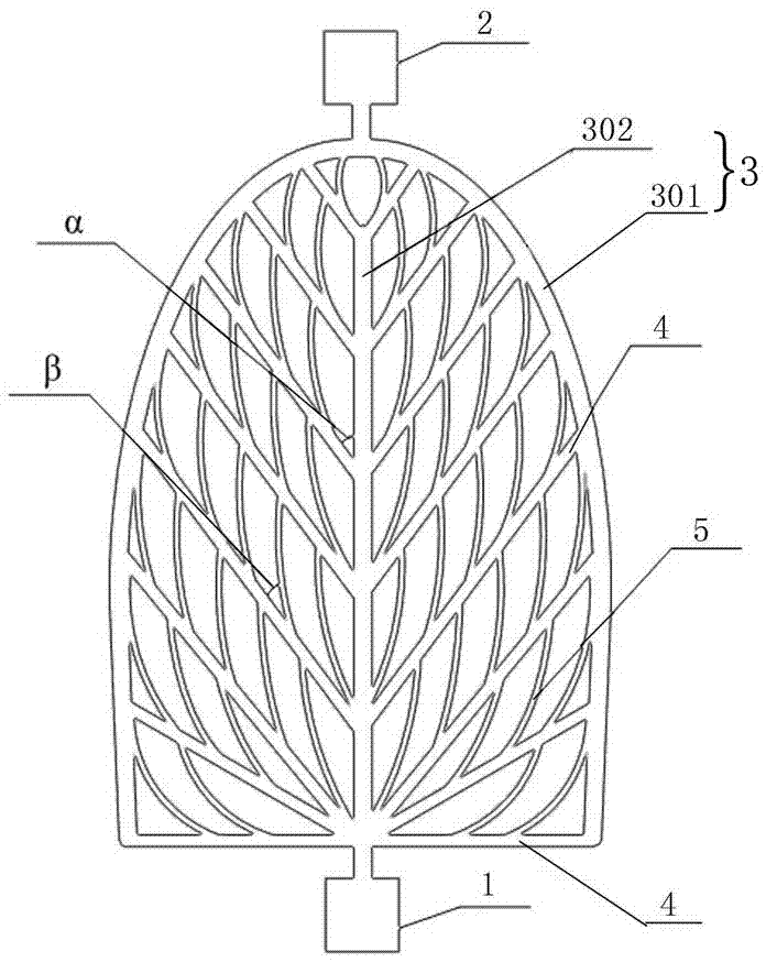
[0018] Using the published MEMS technology, the anode flow field plate channel with a depth of 100µm is etched on the silicon base structure. According to the vein structure of leaves in nature, three levels of flow channels were designed. The diameter of the primary flow channel 3 is 200 μm, the diameter of the secondary flow channel 4 is 160 μm, and the diameter of the third level flow channel 5 is 120 μm.

[0019] The primary flow channel includes an outer flow channel 301 and an intermediate flow channel 302 , the intermediate flow channel 302 is arranged along the center line of the outer flow channel 301 , and the feed port 1 is connected to the front end of the intermediate flow channel 302 . The outer flow channel 301 is a semi-elliptical structure, and the discharge port 2 is set on the top of the semi-elliptical structure. The size of feed port 1 and discharge port 2 is 1x1mm.

[0020] A number of linear secondary flow channels 4 are symmetrically arranged on both s...

Embodiment 2

[0023] The difference from Example 1 is that SU-8 is used as the flow field plate material, and the anode flow field plate channel with a depth of 200 μm is etched on the substrate of this material. The diameter of the primary channel is 200µm, the diameter of the secondary channel 4 is 140µm, and the diameter of the tertiary channel 5 is 98µm.

Embodiment 3

[0025] The difference from Example 1 is that PDMS glue is used as the flow field plate material, and the anode flow field plate channel with a depth of 150 μm is etched on the substrate of the material. The diameter of the primary channel is 200µm, the diameter of the secondary channel 4 is 160µm, and the diameter of the tertiary channel 5 is 128µm.


PUM


Abstract

The invention relates to an anode flow field plate of a methanol fuel cell. A flow channel of the anode flow field plate comprises a first level flow channel, second level flow channels and third level flow channels, and the ratio of the diameters of each second level flow channel to the first level flow channel and the ratio of the diameters of each third level flow channel to each second level flow channel are 0.7-0.8; the first level flow channel comprises an outer flow channel and a middle flow channel, the middle flow channel is arranged along the central line of the outer flow channel, a feed opening is connected with the front end of the middle flow channel, and a discharge opening is connected with the tail end of the outer flow channel; the plurality of second level flow channels are symmetrically arranged on both sides of the middle flow channel and are connected with the outer flow channel and the middle flow channel; one end of the third level flow channel close to the discharge opening is connected with the second level flow channels, the other end of the third level flow channel is connected with the outer flow channel, and the rest third level flow channels are connected with adjacent second level flow channels on the same side. The third level flow channels are of leave fractal structures, thereby abiding by the existence law of vein structures in the nature, helping to make full use of the space of the flow field plate and facilitating to improve the fuel utilization rate, the elasticity is high, the structural strength is high and the occupied volume is small.

Description

technical field [0001] The invention relates to a methanol fuel cell anode flow field structure. Background technique [0002] Direct methanol fuel cells use liquid methanol as fuel, which has the characteristics of easy portability and storage, high specific energy density and high specific power density, and is recognized as one of the best candidates for future small portable mobile power sources. The flow field plate is an important part of the fuel cell. Whether its structural design is reasonable or not is not only related to whether the fuel concentration distribution is uniform, whether the mass transfer and diffusion of the fuel are sufficient, but also determines the output performance of the battery to a certain extent. [0003] The respiratory system, blood circulation system of animals, and the nutrient transmission system inside plants all have similar transport microtubule systems. After hundreds of millions of years of evolution, these microtubule systems of ...

Claims


Application Information

Patent Timeline
Patent Type & Authority Patents(China)
IPC IPC(8): H01M4/86H01M8/0258H01M8/0263
CPCY02E60/50
Inventor 朱平李锦明郭淳吕晓静蔡婷
Owner ZHONGBEI UNIV
Why Eureka
Eureka Blog
Learn More