Hot stamping production line

A hot stamping forming and production line technology, which is applied to forming tools, feeding devices, positioning devices, etc., can solve the problems of long occupation time of robots, decreased production efficiency, large floor space, etc., and achieves simple structure and small heat loss. , the effect of reducing the area

Active Publication Date: 2017-11-28
SUZHOU PRESSLER ADVANCED FORMING TECHNOLOGIES CO LTD
View PDF4 Cites 0 Cited by
  • Summary
  • Abstract
  • Description
  • Claims
  • Application Information

AI Technical Summary

Problems solved by technology

Since the billet needs to be continuously fed into the press while being heated and kept warm, and the heating and holding time needs at least 300 seconds, this requires the transfer time of the billet from the inlet end to the outlet end in the furnace cavity to be 300 seconds, and it is also necessary to ensure that the heating furnace It can support the production volume of the press, that is, to ensure a certain production cycle. Therefore, the furnace of the heating furnace of this kind of production line is very long, usually tens of meters, and covers a large area.
[0003] The multi-layer box-type heating furnace production line relies on the picker of the same robot to reach into the furnace of each layer of the multi-layer box-type heating furnace, and puts the heated billet from the same furnace door of a certain layer for heating and heat preservation. After picking up and taking out the heated billet, the robot in this way is occupied for a long time, resulting in low production efficiency. At the same time, it takes much longer for the robot end picker / manipulator to pick up and deliver the billet than the billet sent by the roller, which further reduces the production efficiency. decline
Moreover, the end picker of the manipulator must be able to withstand the high temperature in the furnace cavity, so it is necessary to use materials that are resistant to repeated temperature changes, and the cost is high

Method used


Image

  • Hot stamping production line

Examples


Embodiment Construction

[0026] In order to make the above objects, features and advantages of the present invention more comprehensible, specific implementations of the present invention will be described in detail below in conjunction with the accompanying drawings. It should be noted that all the drawings of the present invention are in simplified form and use inaccurate scales, and are only used to facilitate and clearly assist the purpose of illustrating the embodiments of the present invention.

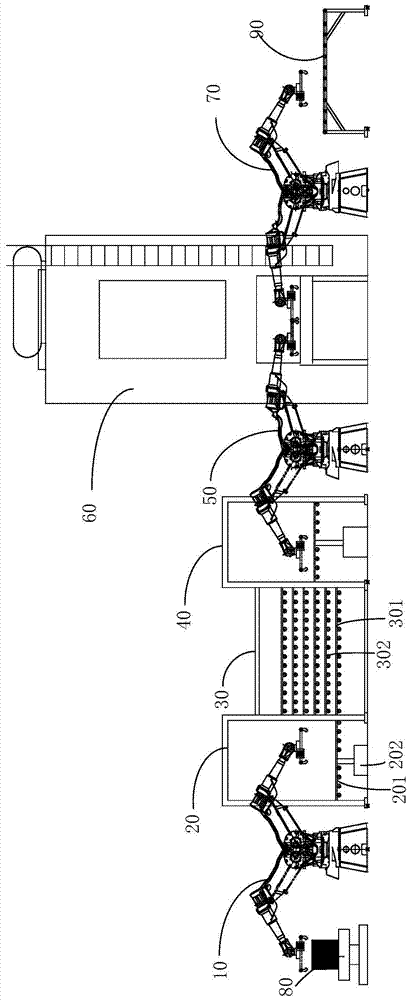
[0027] Such as figure 1 As shown, the hot stamping production line provided by the present invention includes: a feeding robot 10, a first lifting platform 20, a heating furnace 30, a second lifting platform 40, a feeding robot 50, a press 60 and an unloading robot 70 arranged in sequence . Wherein, the heating furnace 30 is a roller hearth type multi-layer heating furnace, and a multi-layer rolling table 301 is arranged in the furnace, and the first and second lift tables 20, 40 both include a transmi...


PUM


Abstract

The invention discloses a hot stamping and forming production line. The hot stamping and forming production line comprises a feeding robot, a first lifting table, a heating furnace, a second lifting table, a conveying robot, a press and a discharging robot which are arranged sequentially, wherein multiple layers of rolling tables are arranged in a hearth of the heating furnace; each of the first lifting table and the second lifting table comprises a conveying platform and a lifting device for driving the conveying platform to lift, and the lifting device and the conveying platform are matched to feed materials to or discharge materials from the rolling tables layer by layer. Through arrangement of the first lifting table and the second lifting table, the rolling table is not required to perform continuous feeding in a single direction, that is, the length of the hearth of the heating furnace is much shorter than that in the prior art, and the occupation area of the production line is reduced greatly. The manipulators are not required to extend into a furnace cavity to grab blanks, the materials in the furnace cavity cannot be bumped against the manipulator and damaged, so that expensive and vulnerable metal materials are not required to be selected, and the production cost is saved; meanwhile, the heat resistance requirement for each manipulator of each robot is low, and the production cost is further saved.

Description

technical field [0001] The invention relates to a hot stamping forming production line. Background technique [0002] The current hot stamping production line is divided into continuous roller hearth heating furnace production line and multi-layer box type heating furnace production line. Among them, in the continuous roller bottom heating furnace production line, the robot sends the heated billet to the rolling inlet end of the heating furnace, and the heated billet is continuously fed and heated by the unidirectional rolling roller in the heating furnace until it is sent to the outlet end of the heating furnace. Then it is picked up by the robot and sent to the press. Since the billet needs to be continuously fed into the press while being heated and kept warm, and the heating and holding time needs at least 300 seconds, this requires the transfer time of the billet from the inlet end to the outlet end in the furnace cavity to be 300 seconds, and it is also necessary to e...

Claims


Application Information

Patent Timeline
Patent Type & Authority Patents(China)
IPC IPC(8): B21D37/16B21D43/04B21D45/06
CPCB21D22/02B21D22/022B21D43/10B21D45/003
Inventor 安健顾晓明
Owner SUZHOU PRESSLER ADVANCED FORMING TECHNOLOGIES CO LTD
Why Eureka
Try Eureka