Seal head polishing machine

A polishing machine and head technology, applied in surface polishing machine tools, grinding/polishing equipment, grinding machines, etc., can solve the problems of unsatisfactory effect, residual cloth wheel pattern, low work efficiency, etc., and achieve good polishing effect, The effect of low rework rate and improved work efficiency

Inactive Publication Date: 2015-06-10
JIANGSU YAFENG TECH GRP CO LTD
View PDF5 Cites 9 Cited by
  • Summary
  • Abstract
  • Description
  • Claims
  • Application Information

AI Technical Summary

Problems solved by technology

[0002] At present, with the progress and development of society and the improvement of people's living standards, the requirements for the required products are getting higher and higher, especially for the appearance of metal and other products, which must have both visual effects and good hand feeling. Therefore, it brings a broad market prospect to the surface treatment of metal and other products; it turns out that people use manual polishing when polishing the head workpiece, the work efficiency is low, and the effect after polishing is not very ideal. After polishing The final product will have defects such as insufficient brightness and residual cloth wheel pattern. For the structure of the existing product, manual polishing can no longer meet the development trend of modern products.

Method used


Image

  • Seal head polishing machine
  • Seal head polishing machine

Examples


Embodiment Construction

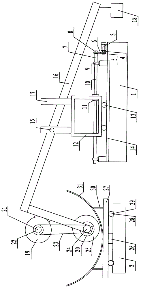
[0009] Attached below picture The specific content of the present invention will be described in detail with specific embodiments.

[0010] Such as picture 1, picture As shown in 2, the head polishing machine includes: a frame 1 and a rotating center seat 2 arranged on the ground, a geared motor 3 is arranged on one end of the frame 1, and a motor shaft 4 of the geared motor 3 A driving sprocket 5 is arranged on the top, and the driving sprocket 5 is connected with the driven sprocket 8 arranged on one end of the transmission shaft 7 through the transmission chain 6, and the two ends of the transmission shaft 7 are arranged on the On the frame 1, a lead screw 10 is provided on the transmission shaft 7 between the two bearing blocks 9, and a lead screw cover 11 cooperating with it is sleeved on the lead screw 10, and the lead screw cover 11 is fixedly arranged On the laterally movable frame 12, the lower end of the laterally movable frame 12 is slidably arranged in the la...


PUM


Abstract

The invention discloses a seal head polishing machine. The seal head polishing machine comprises a rack and a rotary center base which are arranged on the ground, wherein a reducing motor is arranged at one end of the rack; a driving chain wheel is arranged on a motor shaft of the reducing motor and is connected with a driven chain wheel through a transmission chain, and the driven chain wheel is arranged at one end of a transmission shaft; two ends of the transmission shaft are rotationally arranged on the rack through bearing blocks; a lead screw is arranged on the transmission shaft between the two bearing blocks and sleeved with a lead screw sleeve matched with the lead screw; the lead screw sleeve is fixedly arranged on a horizontal moving rack; the lower end of the horizontal moving rack is glidingly arranged in a horizontal track through horizontal rollers; the horizontal track is arranged on the rack; an L-shaped control rod is rotationally arranged at the upper end of the horizontal moving rack through a pin shaft.

Description

technical field [0001] The invention relates to a polishing device, in particular to a head polishing machine. Background technique [0002] At present, with the progress and development of society and the improvement of people's living standards, the requirements for the required products are getting higher and higher, especially for the appearance of metal and other products, which must have both visual effects and good hand feeling. Therefore, it brings a broad market prospect to the surface treatment of metal and other products; it turns out that people use manual polishing when polishing the head workpiece, the work efficiency is low, and the effect after polishing is not very ideal. After polishing The final products will have defects such as insufficient brightness and residual cloth wheel patterns. For the structure of existing products, manual polishing can no longer meet the development trend of modern products. Contents of the invention [0003] The technical p...

Claims


Application Information

Patent Timeline
Patent Type & Authority Applications(China)
IPC IPC(8): B24B29/02
CPCB24B29/02B24B27/0084
Inventor 郭友峰
Owner JIANGSU YAFENG TECH GRP CO LTD
Why Eureka
Try Eureka