
Multi-stage sealing transformation feeding system

A feeding system and sealing cavity technology, applied in the field of multi-stage sealed variable pressure feeding system, can solve problems such as affecting the safe, stable and reliable operation of high-voltage equipment, harsh working environment of variable pressure silo, and prolonging feeding time. , to achieve the effect of simple structure, easy maintenance and low engineering cost

Active Publication Date: 2015-06-10
SOUTHEAST UNIV
View PDF11 Cites 4 Cited by
  • Summary
  • Abstract
  • Description
  • Claims
  • Application Information

AI Technical Summary

Problems solved by technology

As a high and low pressure alternating system, the variable pressure silo is connected to the normal pressure silo and the high pressure silo. It is necessary to switch between low pressure and high pressure frequently during work. The working environment of the variable pressure silo is very harsh and is prone to failure.
Lock bucket tanks are prone to "bridging" during the feeding process, resulting in unsmooth feeding, and need to break the bridge several times to complete feeding, which prolongs the feeding time and affects the safe, stable and reliable operation of high-pressure equipment

Method used


Image

  • Multi-stage sealing transformation feeding system
  • Multi-stage sealing transformation feeding system

Examples


Embodiment Construction

[0020] The present invention will be further explained below in conjunction with the embodiments and the accompanying drawings.

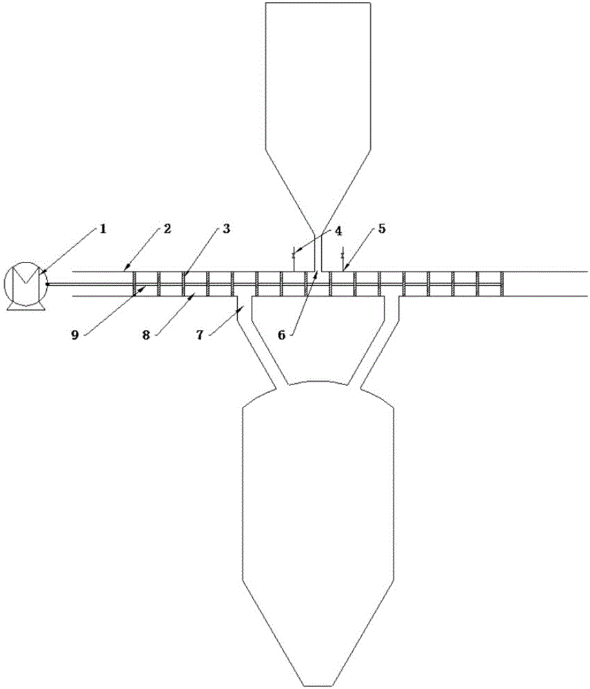
[0021] figure 1 It is a schematic diagram of the conveying device of the multi-stage sealed pressure-changing feeding system. The piston 3 is connected to each other through the connecting rod 9 to form a plurality of independent sealed chambers 8 in the conveying pipeline 2. These sealed chambers 8 form 8 groups of sealed chambers, and the power unit 1 Driven by the driving force, it reciprocates in the conveying pipeline 2. When the sealed chamber 8 on one side is feeding the high-pressure silo, the sealed chamber 8 on the other side is fed through the feeding port 6, which makes every moment, There are corresponding sealing chambers 8 for feeding, pressurizing, discharging and decompressing the high-pressure silo, respectively, so as to ensure the continuity and stability of feeding.

[0022] figure 2 It is a schematic diagram of a multi-stage...


PUM


Abstract

The invention provides a multi-stage sealing transformation feeding system. The multi-stage sealing transformation feeding system comprises a power device, a connecting rod, pistons, a conveying pipeline, a pressure reducing valve, a filtering device, a feeding opening and a discharging opening. All the pistons are connected in the conveying pipeline through the connecting rod to form a plurality of movable sealing chambers and are driven by the power device to carry out reciprocating motion. When the sealing chambers pass through the feeding opening, materials are added; when the sealing chambers pass through the discharging opening, the materials are fully mixed with high-pressure gas in a high-pressure material bin, have the properties of fluid and fall into the discharging opening under the action of gravity. When the sealing chambers run to a reciprocating motion extreme position and then return to the discharging opening, the pressures of the sealing chambers and the high-pressure material bin are balanced, and the remaining materials in the sealing chambers fall into the discharging opening under the action of the gravity. The no-load sealing chambers continuously run, and when the no-load sealing chambers pass through the pressure reducing valve, the pressure is reduced to the normal pressure; the sealing chambers return to the feeding opening for next-round feeding.

Description

technical field [0001] The invention belongs to the field of clean coal power generation and chemical industry, and relates to a multi-stage sealed pressure-changing feeding system. Background technique [0002] As a new type of continuous conveying device, pneumatic conveying system is widely used in energy, chemical industry and other fields. In the high-pressure dense-phase pneumatic conveying system, a variable pressure chamber is used to pressurize the pulverized coal gas flow at atmospheric pressure. As a high-low voltage alternating system, the variable pressure silo is connected to the normal pressure silo and the high pressure silo. It is necessary to switch between low pressure and high pressure frequently during work. The working environment of the variable pressure silo is very harsh and is prone to failure. Lock bucket tanks are prone to "bridging" during the feeding process, resulting in unsmooth feeding, and need to break the bridge several times to complet...

Claims


Application Information

Patent Timeline
Patent Type & Authority Applications(China)
IPC IPC(8): B65G53/52
Inventor 梁财谭震陈晓平刘道银段伦博陈惠超
Owner SOUTHEAST UNIV
Learn More