Bidirectional hinge support device

A two-way hinge and fixed support technology, applied in the direction of measuring devices, transmission parts, instruments, etc., can solve the problems of high noise in the test environment, low test efficiency, heat at the connection between the wire rope and the pulley, etc., and achieve small load fluctuations, Improved test efficiency and good test environment

Inactive Publication Date: 2015-06-10
CHINA HELICOPTER RES & DEV INST
View PDF9 Cites 8 Cited by
  • Summary
  • Abstract
  • Description
  • Claims
  • Application Information

AI Technical Summary

Problems solved by technology

[0003] In the prior art, the fatigue test of the main propeller hub connector assembly adopts the "resonance method" of mechanical vibration loading of the motor at the end of a cantilever beam hinged at one end, and it is difficult to accurately simulate the bending moment distribution of the support arm, and it is difficult to apply a pitch-variable tie rod It is difficult to meet the precision requirements of centrifugal force. Part of the test connection area, especially the connection between the steel wire rope and the pulley, is seriously heated, which is likely to cause the breakage of the centrifugal force loaded steel wire rope and the connecting fixture. The test environment is noisy and affects the monitoring of the test status.
[0004] The above method cannot truly simulate the load transfer relationship, and there is a large engineering simplification. Considering this factor, the total error of the test can reach about 10%. Due to the high environmental noise and severe heating in some connection areas, the test bench needs to frequently replace fixtures and perform maintenance. processing, low test efficiency

Method used


Image

  • Bidirectional hinge support device
  • Bidirectional hinge support device
  • Bidirectional hinge support device

Examples


Embodiment Construction

[0025] The present invention will be described in further detail below.

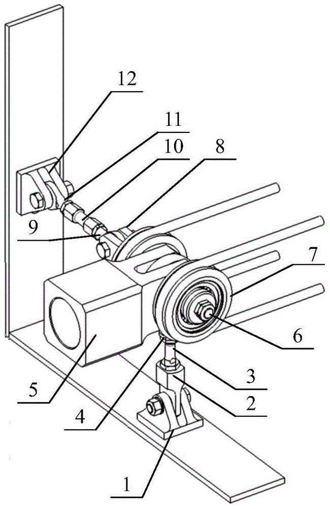
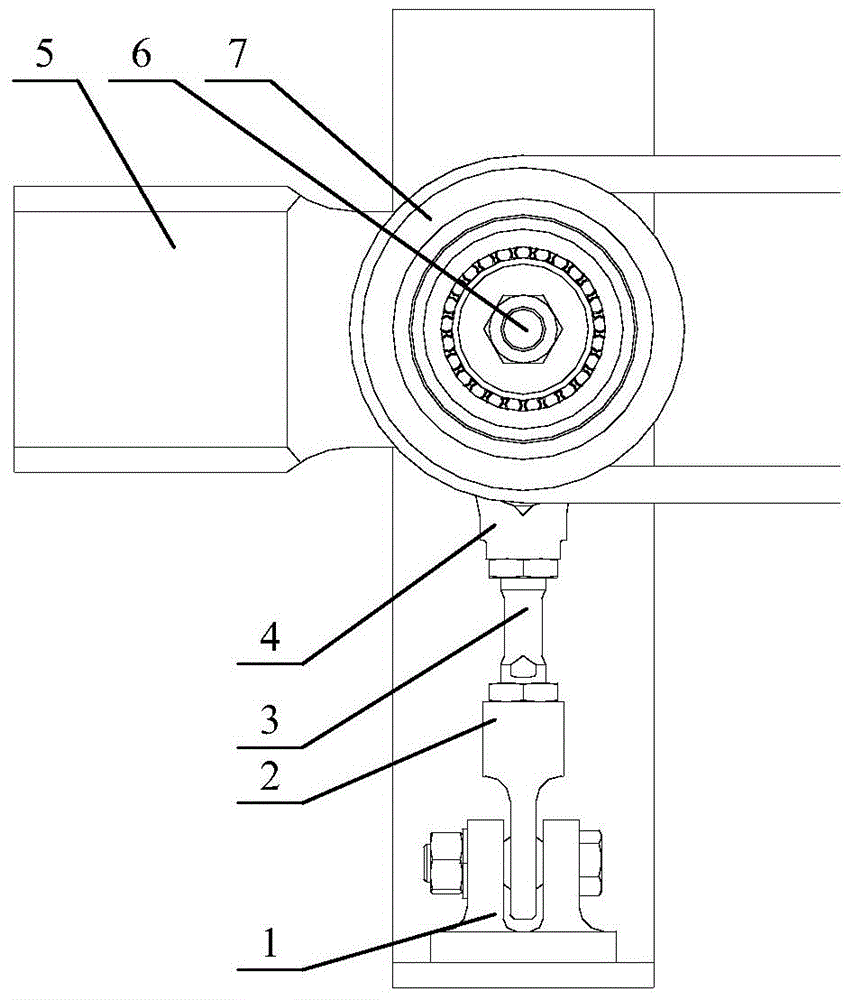
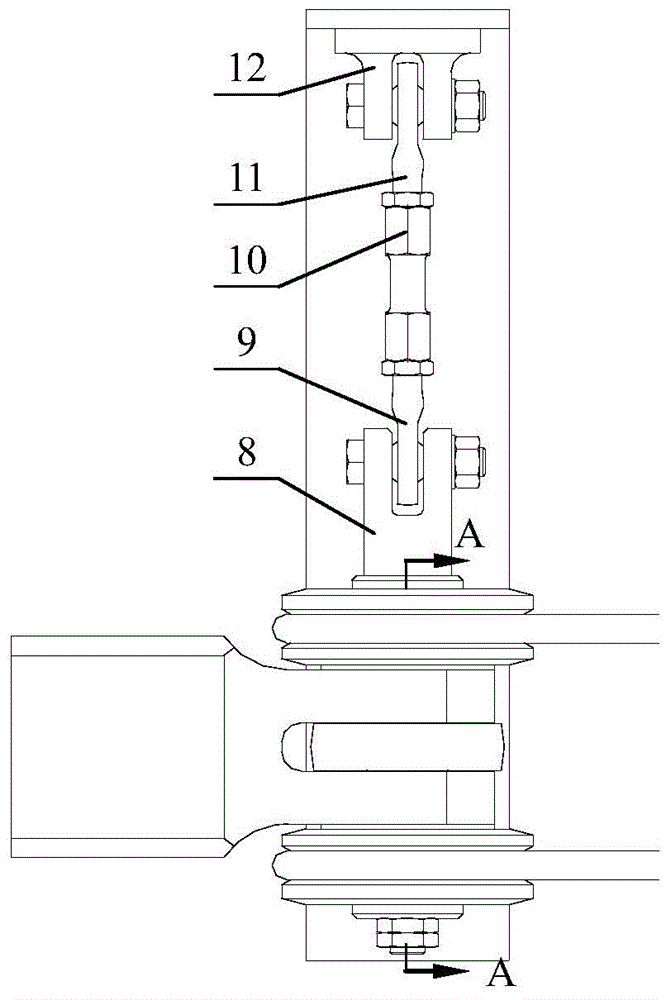
[0026] Such as figure 1 , figure 2 , image 3 , Figure 4 As shown, the present invention is a two-way hinge bearing device, comprising:

[0027] Including the No. 1 fixed support 1, the No. 1 shank joint bearing assembly 2, the swing force measuring rod 3, the shank spherical roller bearing assembly 4, the simulated blade connection joint 5, the connection pin 6, the wire rope pulley assembly 7, the connection support Seat 8, No. 2 shank joint bearing assembly 9, shimmy force measuring rod 10, No. 3 shank joint bearing assembly 11, No. 2 fixed support 12; swinging force measuring rod 3 is a rod-shaped structure with external threads at both ends , the shimmy force measuring rod 10 is a rod-shaped structure with internal threads at both ends, one end of the No. 1 fixed support 1 is fixedly connected with the No. One end of the force bar 3 is connected; the other end of the swinging force bar 3 is c...


PUM


Abstract

The invention discloses a bidirectional hinge support device, and belongs to fatigue test technologies for main hub connecting piece assemblies. The bidirectional hinge support device is characterized by comprising a first fixing support (1), a first joint bearing assembly (2) with a handle, a waving force measuring rod (3), a spherical roller bearing assembly (4) with a handle, an simulation paddle connector (5), a connecting pin (6), a steel wire rope pulley assembly (7), a connecting support (8), a second joint bearing assembly (9) with a handle, a swing vibration force measuring rod (10), a third joint bearing assembly (11) with a handle and a second fixing support (12). The bidirectional hinge support device has the advantages that displacement in waving and swing vibration directions can be constrained, boundary conditions of connecting pieces can be accurately simulated during tests, test beds are stable, test environments are good, the bidirectional hinge support device is low in load fluctuation, total test errors can be within 3% under the control when the tests are carried out by the aid of the bidirectional hinge support device, the tests can be continuously carried out, and the test efficiency can be doubled at least.

Description

technical field [0001] The invention belongs to the fatigue test technology of main propeller hub connector components, and relates to a two-way hinge support device. Background technique [0002] The main hub connector assembly is a typical complex key component in the helicopter structure. The loads transmitted by the blades, including centrifugal force, flapping moment, and shimmy bending moment, are transmitted to the central part through the connector assembly. Balance damper force and pitch rod force. Due to the complex shape of the structure, the severe load it bears, and the lightest possible weight, it is very important to provide an accurate fatigue test assessment environment and conduct test assessment to obtain the real fatigue performance and weak parts to provide a basis for determining its service life. [0003] In the prior art, the fatigue test of the main propeller hub connector assembly adopts the "resonance method" of mechanical vibration loading of the...

Claims


Application Information

Patent Timeline
Patent Type & Authority Applications(China)
IPC IPC(8): G01M13/00F16H57/00
Inventor 李清蓉喻溅鉴邓文李艳艳
Owner CHINA HELICOPTER RES & DEV INST
Why Eureka
Try Eureka