Pico-second laser combined machining SLM device and laser rapid prototyping methods

A technology of laser rapid prototyping and composite processing, which is applied in the direction of additive processing, process efficiency improvement, and energy efficiency improvement. Reduce Workflow Effects

Active Publication Date: 2015-06-17
XIAN BRIGHT ADDTIVE TECH CO LTD
View PDF6 Cites 9 Cited by
  • Summary
  • Abstract
  • Description
  • Claims
  • Application Information

AI Technical Summary

Problems solved by technology

[0003] The purpose of the present invention is to provide a picosecond laser compound processing SLM equipment, which solves the problems of complex working process of SLM equipment and low surface treatment accuracy of parts in the prior art

Method used


Image

  • Pico-second laser combined machining SLM device and laser rapid prototyping methods
  • Pico-second laser combined machining SLM device and laser rapid prototyping methods

Examples


Embodiment 1

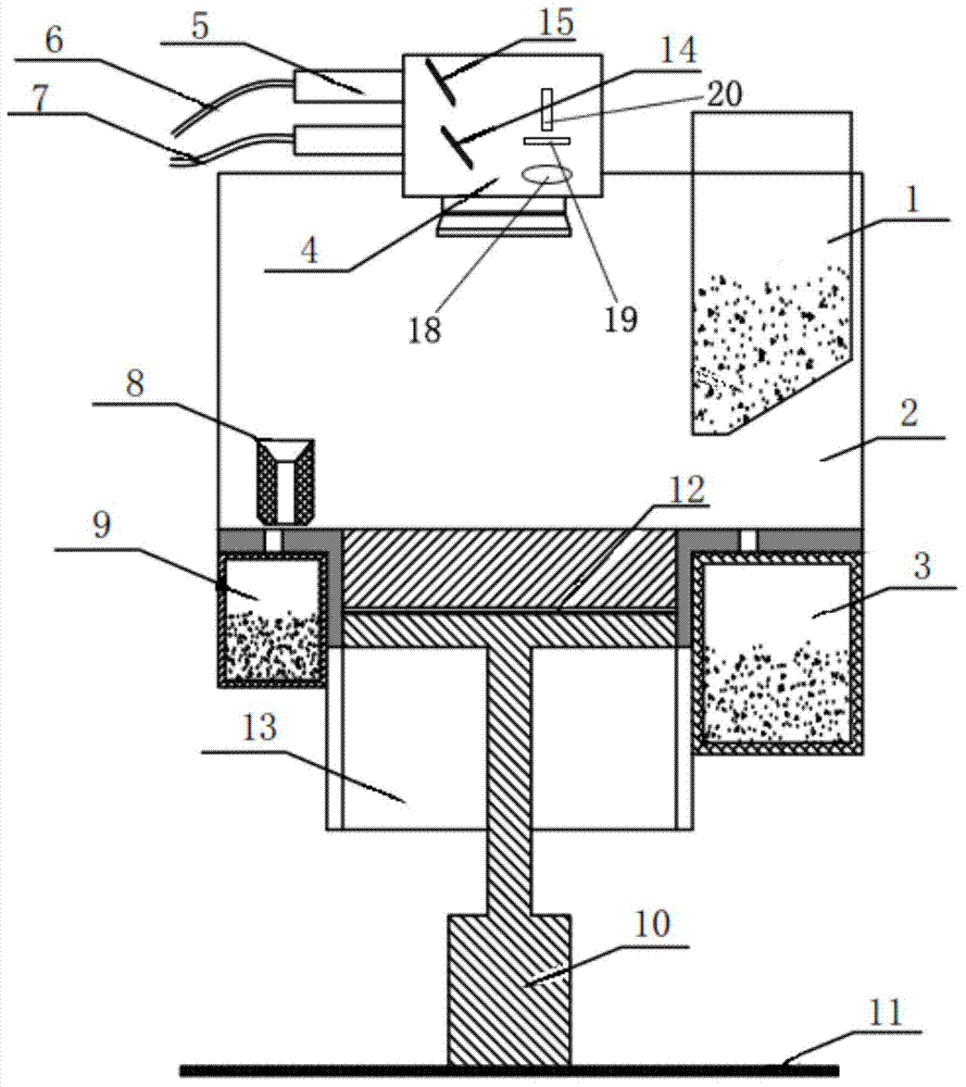
[0033] A picosecond laser compound processing SLM equipment, such as figure 1 As shown, including a work platform 11, the work platform 11 is provided with a motor unit 10, the motor unit 10 is provided with a restraint cylinder 13, the restraint cylinder 13 is used to assemble the formed parts, and the restraint cylinder 13 is connected with a bearing platform 12 for placing parts. The powder spreading system is provided on the carrying platform 12, the powder spreading system includes the powder collecting barrel a3 and the powder collecting barrel b9 arranged on both sides of the restraining cylinder 13, the powder spreading system also includes a scraper 8 arranged on the carrying platform 12 and a The powder-carrying barrel 1 above the carrying platform 12 is provided with a sealed cabin 2 on the bearing platform 12, the powder spreading system is inside the sealed cabin 2, and the upper part of the sealed cabin 2 is provided with a vibrating mirror unit 4. The vibrating m...

Embodiment 2

[0035] On the basis of Embodiment 1, the first lens may also be a beam splitter.

Embodiment 3

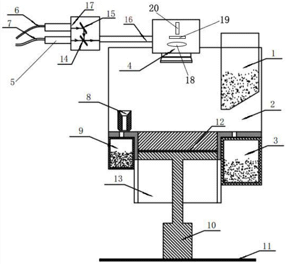
[0037] A picosecond laser compound processing SLM equipment, such as figure 2 As shown, including a work platform 11, the work platform 11 is provided with a motor unit 10, the motor unit 10 is provided with a restraint cylinder 13, the restraint cylinder 13 is used to assemble the formed parts, and the restraint cylinder 13 is connected with a bearing platform 12 for placing parts. The powder spreading system is provided on the carrying platform 12, the powder spreading system includes the powder collecting barrel a3 and the powder collecting barrel b9 arranged on both sides of the restraining cylinder 13, the powder spreading system also includes a scraper 8 arranged on the carrying platform 12 and a The powder-carrying barrel 1 above the carrying platform 12 is provided with a sealed cabin 2 on the bearing platform 12, the powder spreading system is inside the sealed cabin 2, and the upper part of the sealed cabin 2 is provided with a vibrating mirror unit 4. The vibrating ...


PUM


Abstract

The invention discloses a pico-second laser combined machining SLM device. The pico-second laser combined machining SLM device comprises a bearing platform used for placing components and parts, a sealing cabin is arranged on the bearing platform, a galvanometer unit is arranged on the upper portion of the sealing cabin, and the galvanometer unit is connected with a pico-second laser and an ordinary laser through a laser beam processing unit. The invention further provides two laser rapid prototyping methods using the pico-second laser combined machining SLM device. The laser rapid prototyping methods comprise the steps that a three-diamensional model of a part is subjected to hierarchical slicing, and a two-dimensional model of each layer is subjected to main body sintering first and then contour sintering. The problems that the working process of a SLM device in the prior art is complex, the precision of the surface treatment of the part is not high, so that the later additional handling work of the part is tedious, and the labor is consumed are solved.

Description

technical field [0001] The invention belongs to the technical field of laser rapid prototyping, and in particular relates to a picosecond laser compound processing SLM equipment, and the invention also relates to a laser rapid prototyping method. Background technique [0002] Selective laser melting SLM is a method of laser stereoforming and the latest technical means of rapid prototyping technology. SLM equipment is laser rapid prototyping equipment. However, the selective laser melting SLM equipment at this stage is processed and sintered by a single laser, and the formed parts need to be processed again to make the surface smooth, and the whole working process is complicated, and the precision of the surface treatment of the parts is not high, which makes the parts later The surface treatment work is also cumbersome, labor-intensive and time-consuming. Contents of the invention [0003] The purpose of the present invention is to provide a picosecond laser compound proc...

Claims


Application Information

Patent Timeline
Patent Type & Authority Applications(China)
IPC IPC(8): B22F3/105B33Y30/00B33Y10/00
CPCY02P10/25
Inventor 薛蕾杨东辉
Owner XIAN BRIGHT ADDTIVE TECH CO LTD
Why Eureka
Try Eureka