
Pushing ram support device and pushing machine

A technology of supporting device and coke pushing rod, which is applied in unloading device, coke oven, petroleum industry, etc., can solve the problems of tooth gnawing, crushing, affecting the normal operation of production, etc., and achieve the effect of preventing deformation problems.

Active Publication Date: 2015-06-17
SHANDONG IRON & STEEL CO LTD
View PDF4 Cites 4 Cited by
  • Summary
  • Abstract
  • Description
  • Claims
  • Application Information

AI Technical Summary

Problems solved by technology

The deformation of the focus pusher rod will bring a series of problems, such as the beating of the bearing seat of the focus pusher main drive gear, the bad meshing of the focus pusher driving gear and the rack of the focus pusher rod, the phenomenon of teeth gnawing, the accelerated wear of the bottom plate of the pusher rod slide shoe, and the rapid wear of the focus pusher current. Significantly enlarged, the bricks at the bottom of the carbonization chamber are broken due to the vibration of the rod head caused by the sagging of the rod head, etc., which may easily cause the furnace to be shut down for hot repair. The above problems seriously affect the normal operation of production
[0003] In the prior art, there are two main methods to solve the deformation of the focus pusher rod, one is to replace the focus pusher rod, which is costly and time-consuming; the other is to use flame correction technology on the focus pusher rod, but this This technique has a high degree of difficulty and is not easy to master, and the success rate of one correction is low, requiring multiple corrections, which takes a long time. The above two methods are to replace or correct the focus pusher after the focus pusher is deformed. Problems that take a long time and affect the normal production

Method used


Image

  • Pushing ram support device and pushing machine
  • Pushing ram support device and pushing machine
  • Pushing ram support device and pushing machine

Examples


Embodiment Construction

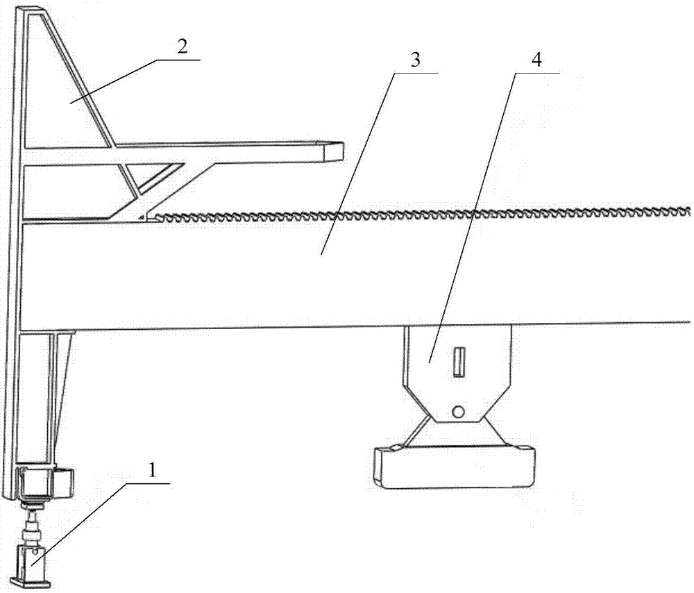
[0029] The invention provides a coke pusher rod support device and a coke pusher car to protect the coke pusher rod from deformation, thereby shortening the maintenance time and frequency of the coke pusher rod, and reducing the furnace shutdown hot repair caused by the coke pusher rod , The purpose of ensuring the normal progress of production.

[0030] The following will clearly and completely describe the technical solutions in the embodiments of the present invention with reference to the accompanying drawings in the embodiments of the present invention. Obviously, the described embodiments are only some, not all, embodiments of the present invention. Based on the embodiments of the present invention, all other embodiments obtained by persons of ordinary skill in the art without making creative efforts belong to the protection scope of the present invention.

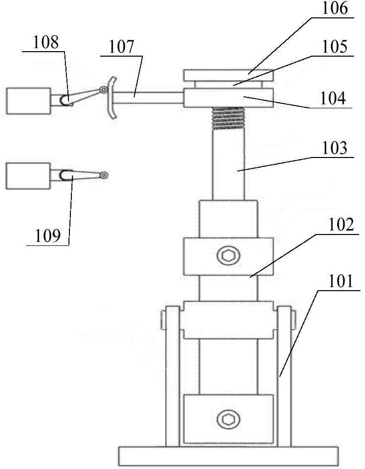
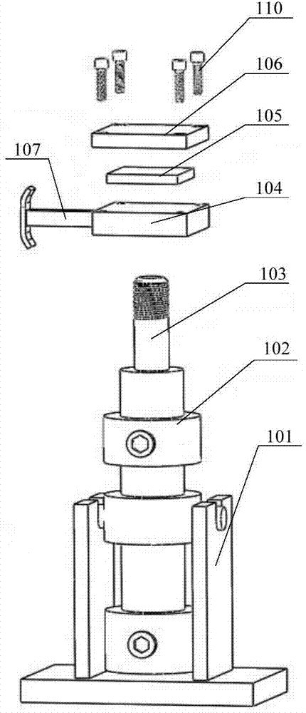
[0031] see Figure 1-Figure 3 , figure 1 Schematic diagram of the structure of the focus pushing rod provided by...


PUM


Abstract

The invention discloses a pushing ram support device which comprises a base, a hydraulic cylinder, a stop device and a hydraulic cylinder control loop, wherein the hydraulic cylinder is arranged on the base, one end of the hydraulic cylinder piston rod away from the cylinder block is provided with a pressure plate for jacking up the pushing ram head, and one side of the pressure plate is provided with a link stopper; the stop device comprises an upper stop plate, a lower stop plate and a signal output device; the distance between the lower stop plate and the pushing machine surface is smaller than that between a pushing ram upper slipper and the pushing machine surface; the hydraulic cylinder control loop is used for driving the hydraulic cylinder piston rod to reciprocate; and when the link stopper contacts the upper stop plate or lower stop plate, the signal output device outputs a signal, and the hydraulic cylinder control loop stops. By adding the pushing ram support device, the deformation of the pushing ram can be avoided from the beginning, thereby reducing the maintenance time and frequency of the pushing ram, reducing the blowout hot repair caused by the pushing ram and ensuring the normal proceeding of the production. The invention also discloses a pushing machine.

Description

technical field [0001] The invention relates to the technical field of coking mechanical equipment, in particular to a coke pushing rod support device and a coke pushing car. Background technique [0002] As the main equipment component of the coke pusher, the coke pusher is responsible for pushing the 1000°C coke out of the coking chamber. When pushing the coke, the coke pushing rod passes through the carbonization chamber at 1350°C driven by the motor. The one-way time is about 50s, and then it stays outside for about 7 minutes, and then pushes the coke for the next furnace. At this time, the overall temperature of the focus pusher rod is high, the strength decreases, and the head of the focus pusher rod is in a suspended state. During the natural cooling process, affected by the weight of the pusher rod head, the focus pusher rod has a tendency to deform, such as pushing Arching of the focus rod, drooping of the head of the push rod, etc. The deformation of the focus pu...

Claims


Application Information

Patent Timeline
IPC IPC(8): C10B33/08
CPCC10B33/08
Inventor 宋一格任维梅宋宪锋姜世远戴孝佩李建郑晓明代淑娟蒋秀香魏述亮
Owner SHANDONG IRON & STEEL CO LTD
Features
  • Generate Ideas
  • Intellectual Property
  • Life Sciences
  • Materials
  • Tech Scout
  • Unparalleled Data Quality
  • Higher Quality Content
  • 60% Fewer Hallucinations
Learn More