Switch magnetic flow arc-shaped permanent magnet motor

A technology of switching magnetic flux and permanent magnet motors, which is applied in the direction of magnetic circuit shape/style/structure, electrical components, electromechanical devices, etc. It can solve the problems of low utilization rate of permanent magnets, low positioning accuracy, slow motion response, etc., and achieve Avoid high temperature demagnetization, high positioning accuracy, and small electromagnetic influence

Inactive Publication Date: 2015-06-17
BEIJING INSTITUTE OF TECHNOLOGYGY
View PDF7 Cites 6 Cited by
  • Summary
  • Abstract
  • Description
  • Claims
  • Application Information

AI Technical Summary

Problems solved by technology

[0004] The purpose of the present invention is to solve the problems of slow motion response, low positioning accuracy, and complex system caused by the indirect drive of the existing scanning mechanism through gears, and to solve the low utilization rate of the permanent magnet caused by the permanent magnet on the mover and the problem of the permanent magnet on the mover. To solve the problem of electromagnetic interference caused by permanent magnets on peripheral electronic equipment, a switch flux arc permanent magnet motor is proposed

Method used


Image

  • Switch magnetic flow arc-shaped permanent magnet motor
  • Switch magnetic flow arc-shaped permanent magnet motor
  • Switch magnetic flow arc-shaped permanent magnet motor

Examples


Embodiment 1

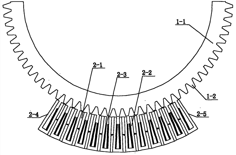
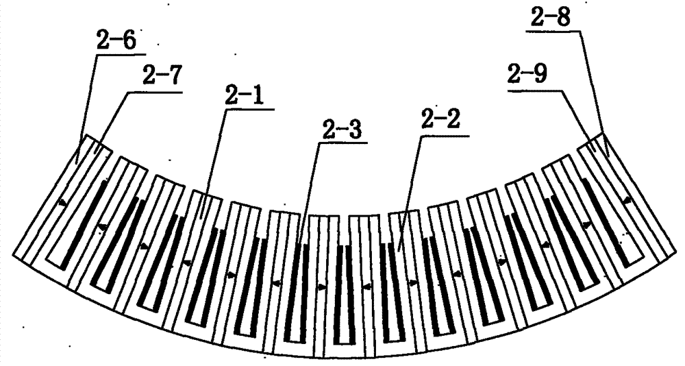
[0020] combine figure 1 This embodiment will be described. This embodiment includes a stator and a mover (1-1). The mover (1-1) is a semi-circular arc-shaped structure made of laminated silicon steel sheets, and several salient poles (1-2) of the same shape are evenly distributed along the circumference; the stator is an arc-shaped structure at a certain angle, composed of N pieces of complete U-shaped iron cores (2-2) and N-1 pieces of permanent magnets (2-1) are closely spaced in sequence. The magnetization direction of adjacent permanent magnets is opposite along the circumferential direction. The permanent magnets can be high-performance rare earth permanent magnets. Magnetic material; stator U-shaped iron core (2-2) is made of laminated silicon steel sheets, and concentrated armature winding (2-3) is placed in U-shaped groove (2-2); number of salient poles (1-2) of mover The number of U-shaped slots (2-2) of the stator is matched according to the mechanism of electromagn...

Embodiment 2

[0022] combine figure 1 To illustrate this embodiment, the difference from Embodiment 1 is that the windings placed in the U-shaped groove (2-2) are three-phase or more than three-phase.

Embodiment 3

[0024] combine figure 1 The present embodiment is different from the first embodiment in that the angle at which the mover (1-1) is larger than the stator is the scanning range of the motor, and the central angle of the stator can be designed according to the scanning range requirements of the motor.


PUM


Abstract

The invention relates to a switch magnetic flow arc-shaped permanent magnet motor, and belongs to the technical field of linear motors. The switch magnetic flow arc-shaped permanent magnet motor comprises a stator and a rotor. The rotor is of a 180-degree circular arc structure formed by overlaying silicon steel sheets; multiple salient poles which are in an identical shape are evenly distributed on the rotor along the circumference. The stator is of a circular arc structure of a certain particular central angle; the stator is composed of thirteen complete U-shaped silicon steel sheet iron cores and twelve permanent magnets which are sequentially and closely arranged at intervals. The central angle of the rotor is larger than the central angle of the stator, and the difference value of the central angle of the rotor and the central angle of the stator is the scanned area of the switch magnetic flow arc-shaped permanent magnet synchronous motor; an air gap is formed between the stator and the rotor; armature windings are placed in the U-shaped iron cores, and the windings are three-phase or multi-phase. The switch magnetic flow arc-shaped permanent magnet motor can directly drive a load which needs to move back and forth within the limited angle, leaves out an indirect driving middle complicated mechanical conversion device, and enables the whole system to be simpler in structure, higher in positioning accuracy and faster in response.

Description

technical field [0001] The invention relates to a switched magnetic flux arc permanent magnet motor which reciprocates within a limited angle and belongs to the technical field of linear permanent magnet motors. Background technique [0002] The existing scanning servo mechanism mostly adopts the indirect drive mode consisting of "high-speed servo motor + gear set + ring gear". This transmission structure through gear meshing inevitably has nonlinear friction, interval dead zone and elastic deformation. , when completing motions such as starting, accelerating, decelerating, reversing, and braking, it is easy to cause system vibration, slow motion response, and poor dynamic stiffness. These inherent defects make the scanning mechanism further improve its speed regulation performance and positioning capabilities. Difficult to achieve technical breakthroughs. The method of direct drive by an arc-shaped torque motor can effectively solve the above problems. The direct-drive ser...

Claims


Application Information

Patent Timeline
Patent Type & Authority Applications(China)
IPC IPC(8): H02K41/03H02K1/16H02K1/17
Inventor 赵静古中鑫刘向东李景琪
Owner BEIJING INSTITUTE OF TECHNOLOGYGY
Why Eureka
Try Eureka