Piezoelectric filter

A filter and piezoelectric technology, which is applied in the field of electronic communication technology devices, can solve the problems of damage to the passband insertion loss and return loss of piezoelectric filters, and achieve the effect of expanding the relative bandwidth

Inactive Publication Date: 2015-06-17
贵州汉天下科技(集团)有限公司
View PDF8 Cites 15 Cited by
  • Summary
  • Abstract
  • Description
  • Claims
  • Application Information

AI Technical Summary

Problems solved by technology

It can be seen from Figure 1(c) that if you increase |f p1 -f s2 The value of |, although the passband of the piezoelectric filter will be expanded, a depression will be formed in the center of the passband of the piezoelectric filter, which greatly damages the passband insertion loss of the piezoelectric filter (please refer to curve 301) and Return loss (please refer to curve 321)

Method used


Image

  • Piezoelectric filter
  • Piezoelectric filter
  • Piezoelectric filter

Examples


Embodiment 1

[0046] Please refer to FIG. 2( a ), which is a circuit structure of a piezoelectric filter according to a specific embodiment of the present invention. As shown in the figure, the piezoelectric filter 400 includes an input port 431, an output port 432, a signal line 40, a series resonator 411, a parallel resonator 421, a first inductor 401, a second inductor 402, a third inductor 403 and a grounding branch Road (constituted by ground inductance 441). Wherein, the signal line 40 connects the input port 431 and the output port 432 in series; the series resonator 411 is connected to the input port 431 and the output port 432 through the signal line 40; one end of the parallel resonator 421 is connected to the signal line 40, specifically the one end Connected to the output port of the series resonator 411, the other end of the parallel resonator 421 is grounded through the third inductance 403; there is a first inductance 401 directly connected to the input port 431 at the input ...

Embodiment 2

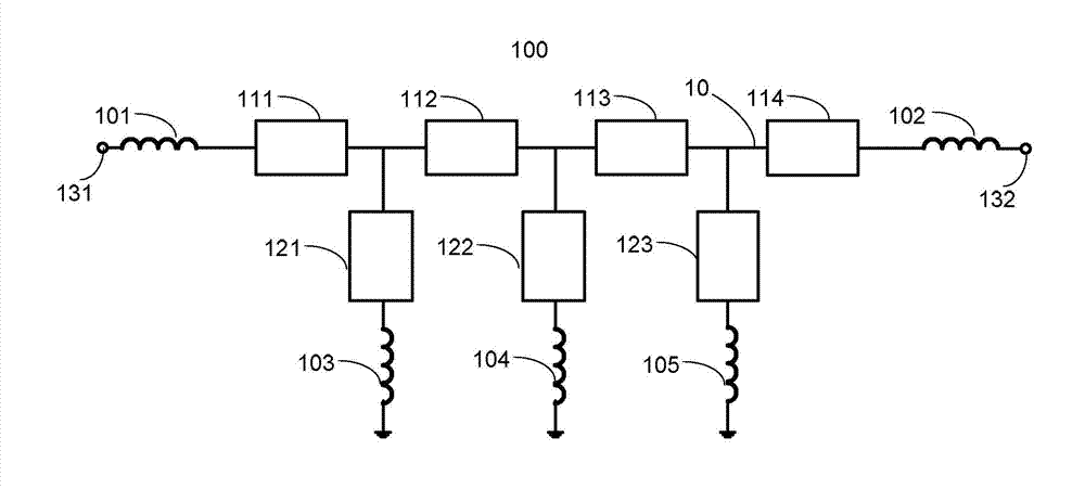
[0049] image 3 is a circuit structure of a piezoelectric filter according to another specific embodiment of the present invention. As shown in the figure, the piezoelectric filter 600 includes an input port 631, an output port 632, a signal line 60, 4 series resonators (respectively series resonators 611, 612, 613, 614), 3 parallel resonators (respectively are parallel resonators 621, 622, 623), the first inductance 601, the second inductance 602, three third inductances (respectively the third inductance 603, 604, 605) and the ground branch (composed of the ground inductance 641) . Wherein, the signal line 60 connects the input port 631 and the output port 632 in series; the series resonators 611, 612, 613, 614 are connected in series between the input port 631 and the output port 632 through the signal line 60; one end of the parallel resonator 621 is connected in series The other end of the output port of the resonator 611 is connected to the ground through the third indu...

Embodiment 3

[0052] Figure 4 is a circuit structure of a piezoelectric filter according to yet another embodiment of the present invention. Figure 4 Piezoelectric filter 700 shown with image 3 The structural difference of the piezoelectric filter 600 shown is only that, on the basis of the piezoelectric filter 600, the piezoelectric filter 700 further includes a grounding branch, which is formed by a grounding inductance 742, wherein, One end of the ground-to-ground inductor 742 is connected to the signal line between the series resonator 714 and the first inductor 702 , and the other end is connected to the ground. For the sake of brevity, the description of the same structure of the piezoelectric filter 700 and the piezoelectric filter 600 will not be repeated here.

[0053] Similarly, under the joint action of the two grounding branches (namely, the grounding inductance 741 and the grounding inductance 742) of the piezoelectric filter 700, its relative bandwidth is not only expanded...


PUM


Abstract

The invention provides a piezoelectric filter which comprises a signal line, at least one first resonator, at least one second resonator and at least one grounding branch. The signal line is used for connecting an input ending opening and an output end opening of the piezoelectric filter. The first resonators are connected to the signal line in series. The second resonators are connected to the signal line in parallel. Nodes on the signal lines are grounded through inductance by means of the grounding branches. By means of the piezoelectric filter, the relative bandwidth of the piezoelectric filter can be expanded effectively on the premise that the performance of the piezoelectric filter is not affected and even improved.

Description

technical field [0001] The invention relates to the field of electronic communication technology devices, in particular to a piezoelectric filter. Background technique [0002] Filter is one of the important components of handheld mobile communication products. At present, handheld mobile communication products mainly use filters made of piezoelectric materials. The basic unit of this high-performance piezoelectric filter is a piezoelectric resonator, and the piezoelectric resonator mainly includes a film bulk acoustic resonator (FBAR). , Solid State Mounted Resonators (SMR) and Surface Acoustic Wave Resonators (SAW). There are two very important frequency points in the impedance-frequency response characteristics of piezoelectric resonators, namely the series resonance frequency f s and the parallel resonant frequency f p . When the piezoelectric resonator is at the series resonant frequency f s When the impedance of the resonator is the lowest, it is close to a short ...

Claims


Application Information

Patent Timeline
Patent Type & Authority Applications(China)
IPC IPC(8): H03H9/46
Inventor 周冲杨清华胡念楚
Owner 贵州汉天下科技(集团)有限公司
Why Eureka
Try Eureka