Rotor combined mixer

A combined type and rotor technology, which is applied in the field of rubber mixing, can solve the problems of uneven proportioning of small materials, increase of silica network structure, uneven proportioning, etc., so as to enhance the secondary strong dispersion effect and increase the effective The temperature control area and the effect of high shear efficiency

Active Publication Date: 2015-06-24
QINGDAO UNIV OF SCI & TECH
View PDF4 Cites 7 Cited by
  • Summary
  • Abstract
  • Description
  • Claims
  • Application Information

AI Technical Summary

Problems solved by technology

At present, the main problem of the internal mixer in the prior art is that it is difficult to control the temperature during rubber mixing, and it is necessary to repeatedly cool the rubber material through deceleration or debinding, especially for rubber materials containing white carbon black formula, temperature control is very important. Its silane coupling reaction is extremely important. If the temperature is low, the silane reaction will be very slow, resulting in a decrease in mixing efficiency; and if the mixing temperature is too high, the silane reaction speed will be faster than the dispersion speed of white carbon black, resulting in silanization. Uneven treatment, increased silica network structure, reduced reinforcement, and even scorch; therefore, most internal mixers usually need to redesign the temperature control system, increase the number of rubber mixing times, and lift the bolt many times. Ensure the smooth completion of the silane coupling reaction and the uniform mixing of the rubber
[0003] However, there are also some novel internal mixers in the prior art that can better solve the above problems, such as a double-station series combined internal mixer disclosed in Chinese patent 200710116412.1, which combines the complete internal mixer of the upper station with the lower one The internal mixer with the top bolt removed is connected with the connecting section barrel, which solves the exhaust problem of the single-station internal mixer, but in actual operation, the carbon black, white carbon black, etc. added to the upper station Due to the low density and easy flying of small materials, part of them is sucked out through the exhaust pipe, and the other part is scattered on the upper part of the upper top bolt, so that the proportion is uneven, which affects the quality of the mixed rubber, and the lower station banburying Although the fast-feeding type low-temperature rotor adopted by the machine solves the problem of feeding materials, it does not have an efficient secondary mixing function, which affects the efficiency of the entire mixing process; a rubber mixing production line disclosed in Chinese patent 201310058124.0 And the rubber mixing method, it connects the small-scale internal mixer, the large-scale internal mixer, the first open mill, multiple second open-rollers in parallel, and the tablet machine in series to form a flow-type production line. The continuous mixing from addition to sheet discharge also fails to solve the problem of uneven proportioning caused by flying and scattering of small materials during feeding, and the rotor is not optimized for design, making the mixing efficiency still relatively low
We know that the performance of the tandem internal mixer mainly depends on the overall continuity and respective division of labor, as well as the good dispersion of the upstream internal mixer, the good cooling efficiency of the downstream internal mixer, the distribution performance of the rubber material and the ability to eat materials, etc. , the upper internal mixer requires a high-dispersion rotor, and the lower one requires a fast-eating low-temperature rotor. Therefore, after long-term painstaking research, the inventor has designed a tandem type that is composed of an upstream meshing rotor and a downstream reaction quadrilateral rotor. The mixing device is used to solve the problems of uneven proportioning and inaccurate temperature control caused by flying and scattering of small materials, which has good application value and market prospect

Method used


Image

  • Rotor combined mixer
  • Rotor combined mixer
  • Rotor combined mixer

Examples


Embodiment 1

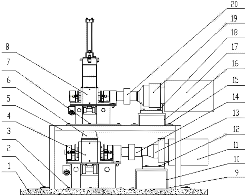
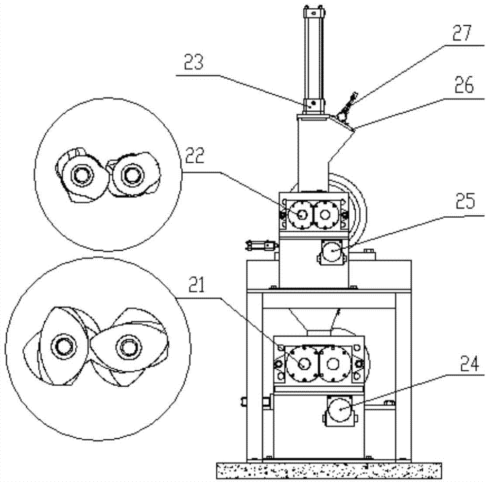
[0017] The main structure of the combined mixing device involved in this embodiment includes a base 1, a first bolt 2, a fourth bolt 3, a downstream mixer 4, a first bracket 5, a connecting device 6, a fifth bolt 7, an upstream mixer 8. The second bolt 9, the second bracket 10, the downstream motor 11, the seventh bolt 12, the downstream reduction box 13, the downstream coupling 14, the third bolt 15, the third bracket 16, the upstream motor 17, the sixth bolt 18 , the upstream reduction box 19, the upstream coupling 20, the reaction square rotor 21 and the meshing rotor 22, the overall device is composed of the upstream internal mixer 8 and the downstream internal mixer 4 connected by the connecting device 6, and the downstream internal mixer 4 The bottom end is fixed on the base 1 by the fourth bolt 3, the downstream motor 11 is connected with the reaction square rotor 21 in the downstream internal mixer 4 through the downstream reduction box 13 and the downstream coupling 14...


PUM


Abstract

The invention belongs to the technical field of rubber mixing and in particular relates to a rotor combined mixer, comprising an upper internal mixer and a lower internal mixer connected in series and equal in size. The upper internal mixer is a small maternal mixer equipped with an automatic cleaner and a meshing rotor of high dispersion and low temperature; the lower internal mixer is a large internal mixer with no top bolt and is equipped with a reaction four-edged rotor having shearing effect of a shearing rotor and distributed mixing action of the meshing rotor. During mixing, the meshing rotor of the upper internal mixer quickly disperses rubber material by high-speed shearing and kneading; the lower internal mixer secondarily mixes the rubber material through a large internal mixing chamber and the reaction four-edged rotor, and thus silylation reactions are ensured being fully and evenly completed at constant temperature. The rotor combined mixer is scientific in design, simple in structure, simple to assemble, easy to temperature-control, safe to operate, good in mixing effect and good in product quality.

Description

Technical field: [0001] The invention belongs to the technical field of rubber mixing, and specifically relates to a rotor combined device, which realizes uniform and high-efficiency continuous mixing through the mutual cooperation of the meshing rotor in the upstream internal mixer and the reaction square rotor in the downstream internal mixer. It solves the technical problems such as the difficulty in controlling the temperature of the traditional internal mixer, the uneven proportioning caused by the flying of small materials, and the low efficiency of secondary mixing. Background technique: [0002] The internal mixer is one of the most important rubber mixing equipment in the modern rubber industry. Since the real Banbury (Benbury) type internal mixer appeared in 1916, it has a series of features superior to the open mixer, such as Large mixing capacity, short time, high production efficiency, better overcome dust flying, reduce the loss of compounding agents, improve p...

Claims


Application Information

Patent Timeline
IPC IPC(8): B29B7/20
CPCB29B7/7466B29B7/7495B29B7/183B29B7/186B29B7/22B29B7/286B29B7/7485B29B7/823
Inventor 边慧光袁浪于本会王蒙潘弋人汪传生
Owner QINGDAO UNIV OF SCI & TECH
Why Eureka
Try Eureka