Electro hydrodynamic preparation device and method for batch micro-droplets and micro-structures

A preparation device and micro-droplet technology, which is applied in printing and other directions, can solve the problems that liquids with low conductivity are not suitable, increase the difficulty and cost of needle technology, and it is difficult to meet batch preparation, so as to achieve rich templates and printing effects. Overcoming the effect of insensitivity to electric field response and easy repeatability of operation steps

Active Publication Date: 2015-06-24
SHANGHAI JIAO TONG UNIV
View PDF10 Cites 26 Cited by
  • Summary
  • Abstract
  • Description
  • Claims
  • Application Information

AI Technical Summary

Problems solved by technology

Therefore, to obtain smaller droplets, smaller needles are required, increasing the technical difficulty and cost of needle preparation
In addition, this mode mostly uses liquids with high conductivity. This kind of liquid has the characteristics of rapid response to the electric field,

Method used


Image

  • Electro hydrodynamic preparation device and method for batch micro-droplets and micro-structures
  • Electro hydrodynamic preparation device and method for batch micro-droplets and micro-structures
  • Electro hydrodynamic preparation device and method for batch micro-droplets and micro-structures

Examples


Example Embodiment

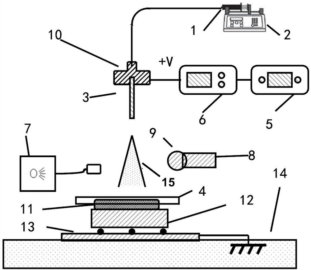
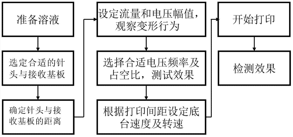
[0063] The present invention also provides a method for preparing batches of micro-droplets and microstructures by electrofluid dynamic preparation, including the following steps, such as figure 1 Shown:

[0064] 1) Select or mix the solution, load it into the syringe 1 and fix it on the micro syringe pump 2;

[0065] 2) According to the selected solution and printing requirements, select the needle 3 and the receiving substrate 4, and determine the distance between the needle 3 and the receiving substrate 4;

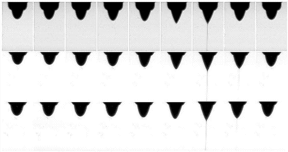
[0066] 3) Connect the high-speed camera 8 and the high-magnification microscope lens 9, set the frame rate and resolution of the high-speed camera 8, set the voltage amplitude and the flow rate of the needle, test the printing effect, and observe the accumulation and ejection of the liquid at the needle 3 in real time In case, adjust the set parameters according to the observation results to obtain a stable printing process;

[0067] 4) According to printing requirements, sele...

Example Embodiment

[0077] Examples:

[0078] Step 1. Select the pure ethylene glycol solution, draw 1ml into the syringe 1 with a capacity of 1ml, and install it on the micro-syringe pump, and push the liquid to the tip of the needle 3 through a hose as a pipeline or directly connected to ensure the liquid Extrude from the inner diameter of the needle and will not adhere to the outer wall of the needle;

[0079] Step 2. Use a stainless steel needle 3 with an inner diameter of 160 μm and an outer diameter of 310 μm. The receiving substrate is a mirror-finished stainless steel disc 4 with a diameter of 10 mm. The receiving substrate and the z-axis rotating platform 12 are sucked and fixed by a vacuum motor 11, the z-axis rotating platform and the x-y motion platform 13 are connected, and the distance between the needle tip and the receiving substrate is set to 1.5mm;

[0080] Step 3. The frame rate of the high-speed camera 8 is set to 10000 frames, the resolution is 372x768, and the magnification of th...


PUM

PropertyMeasurementUnit
Conductivityaaaaaaaaaa
Viscosityaaaaaaaaaa
Surface tensionaaaaaaaaaa

Abstract

The invention provides an electro hydrodynamic preparation device and method for batch micro-droplets and micro-structures. The preparation device comprises a liquid conveying system, an injection receiving system, a voltage control system, a high-speed photographing system and a bottom platform movement control device. The preparation method includes the steps that a micro-injection pump is utilized to push liquid to a needle head tip from an injector according to a certain flow; fluid is gathered at the needle head tip; under the effect of an electric field, the liquid gathered at the needle head forms a Taylor cone, linear liquid ejected from the tip of the Taylor cone falls onto a receiving substrate, and finally deposited droplets are formed. Bottom platform moves to be matched with continuous ejection of the linear liquid, so batch micro-droplets or micro-structures of certain modes can be prepared.

Description

technical field [0001] The invention relates to a device and method for preparing microdroplets and microstructures in batches, in particular to a device and method for batch preparation of microdroplets and microstructures driven by electrohydrodynamics. Background technique [0002] Inkjet printing technology has been widely used in the field of image printing because of its advantages of no template, environmental friendliness, and high printing accuracy, and has been expanded to print electronics, microfluidic chips and other fields, and can be used to prepare biosensors, solar cell chips and microchips. Runner chips, etc. Traditional inkjet printing technology usually adopts two modes of continuous inkjet and on-demand printing. [0003] Continuous inkjet technology is a technology that uses piezoelectric crystal vibration to apply pressure to continuously eject droplets, obtain information on the deflection distance of ink droplets through the control unit according t...

Claims


Application Information

Patent Timeline
IPC IPC(8): B41J2/01B41J2/175
Inventor 熊振华袁鑫盛鑫军朱向阳
Owner SHANGHAI JIAO TONG UNIV
Why Eureka
Try Eureka