
Resonator Element, Electronic Device, Electronic Apparatus, And Moving Object

A technology of vibrating element and vibrating arm, applied in the fields of vibrating element, electronic device, electronic equipment and moving body, can solve the problems of Q value reduction, leakage, error and so on

Inactive Publication Date: 2015-06-24
SEIKO EPSON CORP
View PDF1 Cites 2 Cited by
  • Summary
  • Abstract
  • Description
  • Claims
  • Application Information

AI Technical Summary

Problems solved by technology

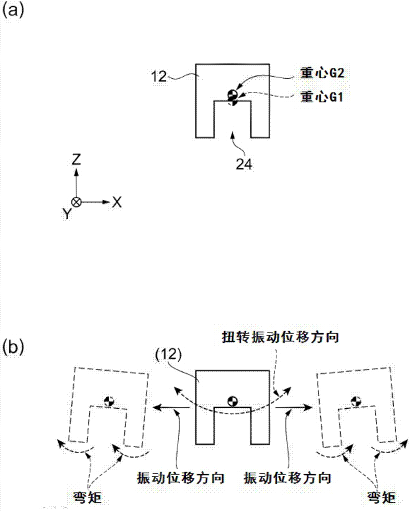
[0004] However, when grooves are formed from one main surface of the vibrating arm by dry etching or the like, and bending vibration is performed to displace the vibrating arm parallel to the main surface, there is a problem that, due to the influence of the bending moment, the Bending vibration is superimposed with torsional vibration, and the vibration leaks to the base that holds the vibrating arm, reducing the Q value
In addition, in the case of an angular velocity sensor, the bending vibration superimposed with the torsional vibration generated by the driving vibrating arm will be transmitted to the detecting vibrating arm via the base, and the detecting vibrating arm will be vibrated, resulting in the following problems. In other words, an output signal (0-point output) is generated even in the state where no angular velocity is applied, resulting in an error
Therefore, in the case of flexurally vibrating the vibrating arm provided with the grooves formed only from one main surface, there is a problem of suppressing the occurrence of torsional vibration.

Method used


Image

  • Resonator Element, Electronic Device, Electronic Apparatus, And Moving Object
  • Resonator Element, Electronic Device, Electronic Apparatus, And Moving Object
  • Resonator Element, Electronic Device, Electronic Apparatus, And Moving Object

Examples


no. 1 approach

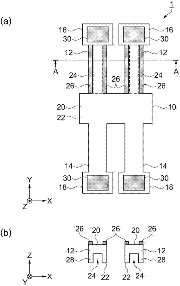
[0056] As an example of the vibrating element according to the first embodiment of the present invention, a vibrating element with a structure called an H type used in an angular velocity sensor is given, and refer to figure 1 Be explained.

[0057] figure 1 It is a schematic diagram showing the configuration of the vibrating element 1 according to the first embodiment of the present invention. figure 1 (a) is a top view, figure 1 (b) for figure 1 (a) A cross-sectional view along line A-A. Also, electrodes for driving and electrodes for detection are omitted. In addition, in each figure, for convenience of description, the X-axis, the Y-axis, and the Z-axis are illustrated as three mutually orthogonal axes, and the tip side of the arrow mark in the illustration is referred to as the "+ side", Set the base end side to "- side". In addition, below, the direction parallel to the X-axis is called "X-axis direction", the direction parallel to the Y-axis is called "Y-axis dire...

no. 2 approach

[0087] Next, refer to Figure 7 as well as Figure 8 , the vibration element 1d according to the second embodiment of the present invention will be described.

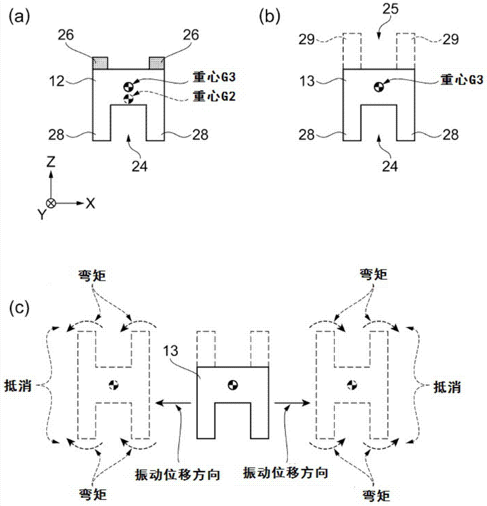
[0088] Figure 7 It is a schematic diagram showing the structure of a vibrating element 1d according to the second embodiment of the present invention. Figure 7 (a) is a top view, Figure 7 (b) for Figure 7 (a) E-E line sectional view. Figure 8 It is a schematic diagram explaining the vibration state of the vibration element 1d according to the second embodiment of the present invention. Figure 8 (a) is a sectional view of the vibrating arm 12, Figure 8 (b) is a sectional view of the imaginary vibrating arm 15, Figure 8 (c) is a sectional view of the virtual vibrating arm 15 showing a vibrating state.

[0089] Hereinafter, the resonator element 1d of the second embodiment will be described centering on the points of difference from the resonator element 1 of the first embodiment described above, and the s...

no. 3 approach

[0094] Next, according to Figure 9 , the vibration element 1e according to the third embodiment of the present invention will be described.

[0095] Figure 9 It is a schematic diagram showing the structure of the vibrating element 1e according to the third embodiment of the present invention. Figure 9 (a) is a top view, Figure 9 (b) for Figure 9 The sectional view of F1-F1 line shown in (a), Figure 9 (c) for Figure 9 (a) F2-F2 line sectional view shown.

[0096] Hereinafter, the resonator element 1e of the third embodiment will be described focusing on the points of difference from the resonator element 1 of the first embodiment described above, and the same reference numerals will be assigned to the same items, and descriptions thereof will be omitted. .

[0097] Such as Figure 9 (a) to Figure 9As shown in (c), the outer shape of the vibrating element 1e of the third embodiment in which the groove portion 24 is provided on the vibrating arm 12 is the same as...


PUM


Abstract

A resonator element inhibiting an unwanted vibration such as a torsional vibration from occurring and having a high Q-value, an electronic device, an electronic apparatus, and a moving object each equipped with the resonator element are provided. The resonator element is provided with a base section, a vibrating arm extending from the base section, and a groove section having a groove with a bottom formed from a first principal surface of the vibrating arm toward a second principal surface on an opposite side to the first principal surface, and is further provided with a mass section disposed on at least a part of the second principal surface.

Description

technical field [0001] The present invention relates to a vibrating element, an electronic device, electronic equipment and a moving body. Background technique [0002] Conventionally, angular velocity sensors have been used to automatically control the attitude of ships, aircraft, rockets, etc. Recently, they have been used in vehicle body control, vehicle position detection in vehicle navigation systems, digital cameras, video recorders, and mobile phones. It is used for control compensation (so-called vibration compensation), etc. Along with the miniaturization of the above-mentioned electronic devices, the angular velocity sensor is also required to be miniaturized and flattened (thinned). [0003] On the other hand, when the vibrating element for an angular velocity sensor having a vibrating arm for driving or detecting is miniaturized, since the area of ​​the electrodes provided on each vibrating arm becomes smaller, the Q value decreases and the detection sensitivity...

Claims


Application Information

Patent Timeline
Patent Type & Authority Applications(China)
IPC IPC(8): H03H9/02H03H9/15
CPCH03H9/1014H03H9/21
Inventor 市川史生
Owner SEIKO EPSON CORP
Learn More