Blood vessel analysis device, medical image diagnostic device, and blood vessel analysis method

A technology for analyzing devices and medical images, used in image analysis, blood flow measurement devices, instruments used for radiological diagnosis, etc. The resulting error becomes larger and other problems

Inactive Publication Date: 2015-06-24
KK TOSHIBA
View PDF5 Cites 13 Cited by
  • Summary
  • Abstract
  • Description
  • Claims
  • Application Information

AI Technical Summary

Problems solved by technology

However, in the case of structure-fluid complex analysis, it is often difficult to accurately set the boundary conditions of the inlet and outlet of blood vessels and the material models of blood vessels and plaques in the fluid analysis of blood (including contrast media).
In addition, when there are tiny blood vessels that are not drawn in the image, there may be cases where the influence of the tiny blood vessels on the blood flow cannot be considered.
Therefore, the analysis results of the structure-fluid composite analysis may not be able to reproduce the actual blood flow and blood vessel deformation
In addition, there are cases where boundary conditions, load conditions, and material models are not appropriate, or where there are problems with convergence and analytical stability in the case of vessels accompanied by large movements
In this way, the conventional structural fluid analysis of blood vessels may require extremely large analysis resources and analysis time, or the error of analysis results may become large, and problems may arise in actual use in the clinical field.

Method used


Image

  • Blood vessel analysis device, medical image diagnostic device, and blood vessel analysis method
  • Blood vessel analysis device, medical image diagnostic device, and blood vessel analysis method
  • Blood vessel analysis device, medical image diagnostic device, and blood vessel analysis method

Examples


Embodiment Construction

[0040] Hereinafter, a blood vessel analysis device, a medical image diagnosis device, and a blood vessel analysis method according to the present embodiment will be described with reference to the drawings.

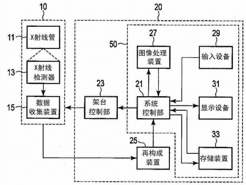
[0041] The blood vessel analysis device according to this embodiment is a computer device for performing structural fluid analysis on a blood vessel region included in a medical image generated by a medical image diagnosis device. The blood vessel analysis device according to the present embodiment may be incorporated in a medical image diagnostic apparatus, or may be a computer device such as a workstation separate from the medical image diagnostic apparatus. Hereinafter, for concrete description, it is assumed that the blood vessel analysis device according to the present embodiment is incorporated in a medical image diagnosis device.

[0042] The medical image diagnostic apparatus according to this embodiment can be applied to any type of image diagnostic apparatus equ...


PUM


Abstract

The present invention enhances the precision of blood vessel structure and fluid analysis. An image analysis / tracking processing unit (53) performs image analysis of a time series medical image and calculates a time series form index and a time series shape deformation index for an analysis subject region. A dynamic model constructing unit (55) provisionally constructs a dynamic model relating to structure and fluid analysis of the analysis subject region on the basis of the time series form index, the time series shape deformation index, and the time series medical image. A statistical identification unit (61) identifies a latent variable relating to a latent variable identification region so that a predicted value for a blood vessel form index and / or a predicted value for a blood vessel flow rate index based on the provisionally constructed dynamic model is / are consistent with an observed value for the blood vessel form index and / or an observed value for the blood vessel flow rate index. Calculation units (57, 59) perform structure analysis, fluid analysis, or structure-fluid interaction analysis on the dynamic model in which the latent variable is allocated to the latent variable identification region, and calculate a predicted value for a time series dynamic index and / or a predicted value for a time series blood flow rate index.

Description

technical field [0001] This embodiment relates to a blood vessel analysis device, a medical image diagnosis device, and a blood vessel analysis method. Background technique [0002] A technique for non-invasively or low-invasively preventing and diagnosing coronary artery stenosis, cerebral aneurysm, or stenosis based on carotid artery plaques as their precursors, which is one of the three major diseases, is desired causes of heart disease. [0003] Stenosis of the coronary arteries is a major lesion leading to ischemic heart disease. As a diagnosis of coronary artery stenosis, coronary angiography (CAG: Coronary Angiography) performed through a catheter is the mainstream. Fractional Flow Reserve (FFR: Fractional Flow Reserve) is used as a diagnostic index for organic coronary artery disease. FFR is defined as the ratio of maximum coronary flow in the presence of stenosis to maximum coronary flow in the absence of stenosis. FFR roughly corresponds to the ratio of the int...

Claims


Application Information

Patent Timeline
Patent Type & Authority Applications(China)
IPC IPC(8): A61B6/03G06T1/00
CPCG06T7/0016G06T2207/10072G06T2207/10136G06T2207/30104A61B6/032A61B6/481A61B6/504A61B6/5217G16H50/30A61B5/02007A61B5/026A61B5/055A61B6/037A61B8/06
Inventor 广畑贤治大贺淳一郎
Owner KK TOSHIBA
Why Eureka
Try Eureka