

Visible intrauterine device extracting instrument
An intrauterine device and IUD technology, applied in the field of medical devices, can solve the problems of aggravating the pain of the patient, affecting the operation efficiency, expensive equipment, etc., so as to reduce trauma and complications, improve operation efficiency, and reduce expenses. Effect
- Summary
- Abstract
- Description
- Claims
- Application Information
AI Technical Summary
Problems solved by technology
Method used
Image

Examples
Embodiment
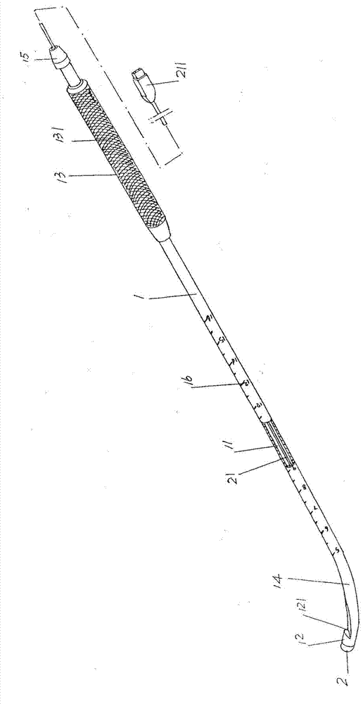
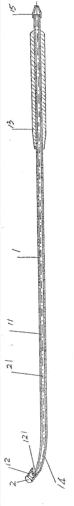
[0023] See figure 1 and figure 2 , provides a catheter 1 with a catheter lumen 11 formed in the center of the length direction, the left end of the catheter 1 forms a hook head 12 for hooking an IUD, and the hook head 12 forms a hook groove 121, And the right end sleeve of conduit 1 inherently has an operating handle 13 .
[0024] As the technical gist of the technical solution provided by the present invention: the structural system of the aforementioned visible intrauterine device removal instrument also includes a miniature camera 2, and the miniature camera 2 is arranged on the end of the aforementioned hook head 12 facing away from the hook groove 121. The end face, that is, is fixed on the left end face of the hook head 12, and the micro camera 2 is drawn from the right end of the catheter lumen 11 after passing through the aforementioned catheter lumen 11 by a micro camera transmission line 21 (also called a micro camera data transmission line). The video device is e...
PUM
| Property | Measurement | Unit |
|---|---|---|
| Outer diameter | aaaaa | aaaaa |
Abstract
Description
Claims
Application Information