a guiding catheter
A catheter and inner tube technology, applied in the field of guiding catheters, can solve problems such as catheter collapse, failure, and inability to enter blood vessels, and achieve the effect of improving the ability to withstand negative pressure and large flow
- Summary
- Abstract
- Description
- Claims
- Application Information
AI Technical Summary
Problems solved by technology
Method used
Image


Examples
Embodiment 1
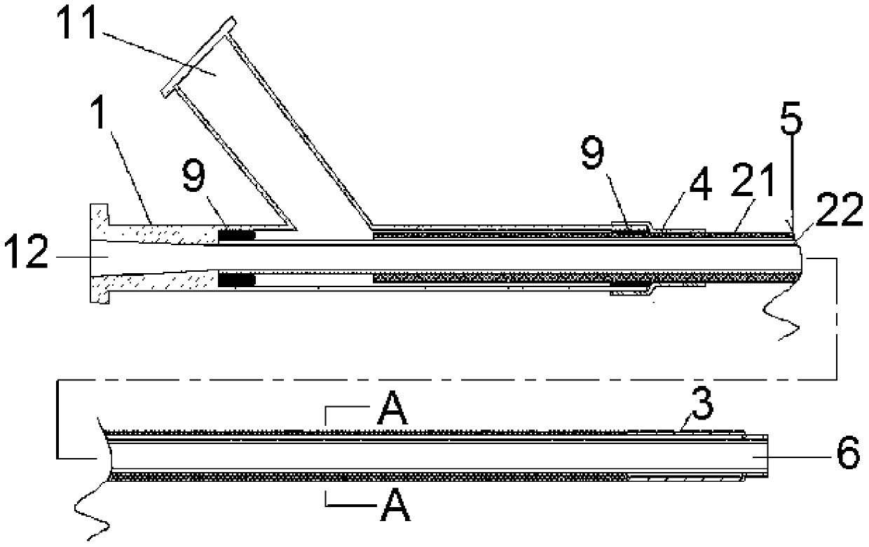
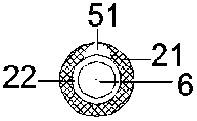
[0032]In this embodiment, three developing points are used, which are respectively arranged at the head end and the middle of the balloon, and the material is silver. The material of the outer tube is PEBAX, and the hardness gradually decreases from the proximal end to the distal end, which are 78D, 55D, and 35D respectively. The inner tube adopts three-layer weaving material, the outer layer is made of polyurethane, the middle layer is made of stainless steel winding wire, the wire width is 0.2mm, and the inner layer is PTFE. The internal diameter of the inner tube is 3mm. The section of the liquid passage chamber 5 adopts a crescent shape. The design length of the head end of the catheter is 3mm. After the overall connection of the catheter is completed, the surface of the catheter is coated with a hydrophilic coating, and the hydrophilic material is selected: sodium hyaluronate.
Embodiment 2
[0034] In this embodiment, two development points are used, which are respectively arranged in the middle of the head end and the balloon, and the material is platinum-iridium alloy. The material of the outer tube is PEBAX, and the hardness gradually decreases from the proximal end to the distal end, respectively 72D, 63D, and 40D. The inner tube is made of three layers of braided material, the outer layer is made of polyurethane, the middle layer is made of stainless steel winding wire, the wire width is 0.15mm, and the inner layer is FEP. The inner diameter of the inner tube is 2 mm, and the liquid passage chamber 54 adopts a double-channel crescent shape. The design length of the catheter tip is 10mm. After the overall connection of the catheter is completed, the surface of the catheter is coated with a hydrophilic coating, and the hydrophilic material is polyvinylpyrrolidone (PVP).
Embodiment 3
[0036] In this embodiment, two developing points are used, which are respectively arranged in the middle of the head end and the balloon, and the material is platinum-iridium alloy. The material of the outer tube is PEBAX, and the hardness gradually decreases from the proximal end to the distal end, respectively 72D, 55D, and 25D. The inner tube is made of three layers of braided material, the outer material is PEBAX, the middle layer is made of nickel-titanium alloy wire, the wire width is 0.15mm, the inner layer is fluororesin (EFEP), and the inner diameter of the inner tube is 1mm. The liquid cavity 56 adopts a three-channel bone shape. The design length of the catheter tip is 15mm. After the overall connection of the catheter is completed, the surface of the catheter is coated with a hydrophilic coating, and the hydrophilic material is polyurethane.
[0037] According to the technical solution of the embodiment of the present invention, the guide catheter is non-coaxial,...
PUM
| Property | Measurement | Unit |
|---|---|---|
| Length | aaaaa | aaaaa |
Abstract
Description
Claims
Application Information
 - Generate Ideas
- Intellectual Property
- Life Sciences
- Materials
- Tech Scout
- Unparalleled Data Quality
- Higher Quality Content
- 60% Fewer Hallucinations
Browse by: Latest US Patents, China's latest patents, Technical Efficacy Thesaurus, Application Domain, Technology Topic, Popular Technical Reports.
© 2025 PatSnap. All rights reserved.Legal|Privacy policy|Modern Slavery Act Transparency Statement|Sitemap|About US| Contact US: help@patsnap.com