Test tube rack for analyzer assembly line and displacement detection method and device of test tube rack

A test tube rack and analyzer technology, used in measuring devices, test tube supports/clamps, analytical materials, etc., can solve problems such as false pulses, missed detection, widening the gap between groove signals and edge signals, and meet performance requirements. The effect of reducing, reducing cost and improving reliability

Active Publication Date: 2015-07-01
SHENZHEN MINDRAY BIO MEDICAL ELECTRONICS CO LTD
View PDF5 Cites 7 Cited by
  • Summary
  • Abstract
  • Description
  • Claims
  • Application Information

AI Technical Summary

Problems solved by technology

However, since the test tube is included in the detection area of ​​the sensor, if the test tube is not affixed with a barcode, the reflection signal of the glass test tube at certain angles may be very strong when the sample is loaded, and a false pulse will be formed if the threshold is exceeded. Even if the test tube is affixed with a barcode, but The surface of some barcode paper is very bright, which may also cause the reflected signal to become very strong and form false pulses
Then there may be multiple pulses higher than the threshold between the two grooves, causing false negative judgments in the case of failure of the test tube rack to shift
That is to say, the test tube rack displacement detection technology has the risk of missed detection of displacement failure, the reliability is not high, and there are still clinical risks
[0005] In addition, the existing detection technology

Method used


Image

  • Test tube rack for analyzer assembly line and displacement detection method and device of test tube rack
  • Test tube rack for analyzer assembly line and displacement detection method and device of test tube rack
  • Test tube rack for analyzer assembly line and displacement detection method and device of test tube rack

Examples


Embodiment 1

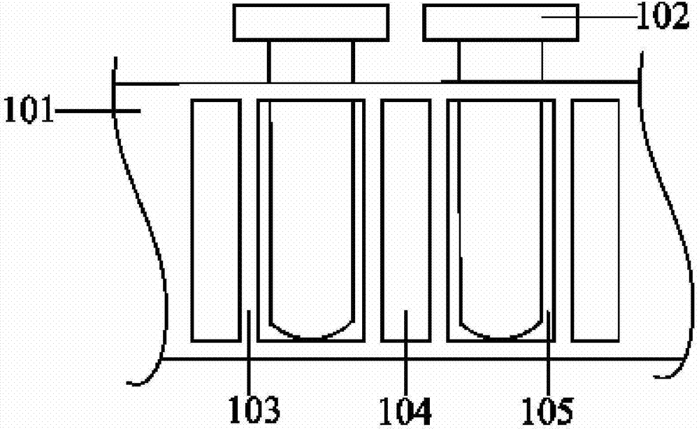
[0034] Please refer to image 3 , this embodiment provides a test tube rack for an analyzer assembly line, the test tube rack is provided with a plurality of test tube positions for accommodating test tubes 301, and one side of the test tube rack (for example, the side facing the light sensor) is provided with The light blocking plate 300 of the position, the second characteristic area 303 is arranged between two adjacent test tube positions on the light blocking plate 300, the first characteristic area 302 is between the adjacent two second characteristic areas 303, the first characteristic area 302 and the second characteristic area 303 have a step difference with a preset depth. The first characteristic regions 302 and the second characteristic regions 303 are arranged alternately and evenly on the light blocking plate 300 .

[0035] In a specific embodiment, the second characteristic region 303 is a groove with a predetermined depth lower than the first characteristic reg...

Embodiment 2

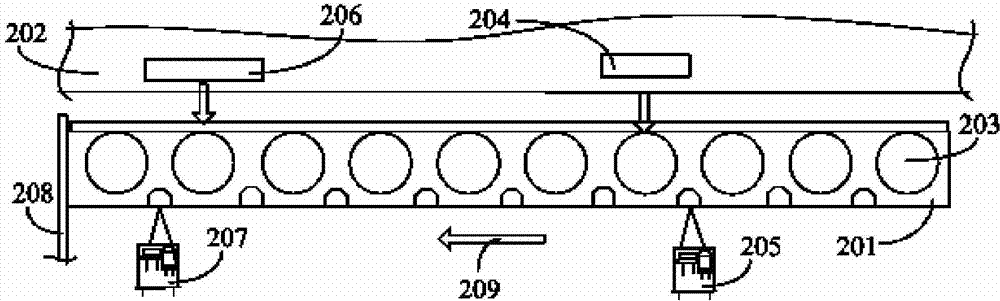
[0043] Please refer to Figure 5 , based on the test tube rack of the analyzer assembly line provided in Embodiment 1, this embodiment provides a method for detecting displacement of the test tube rack correspondingly, including:

[0044] Step 501: Obtain the detection signal output by the sensor during a single displacement of the test tube rack. The shifting of the test tube rack from the start to the stop is a single shift.

[0045] Step 502: Amplify and digitally filter the detection signal to eliminate the interference of noise, local potholes and uneven factors on the surface of the test tube rack, and obtain a more realistic signal. Specifically, a median filtering algorithm may be selected for digital filtering.

[0046] Step 503: Obtain the initial voltage V_ORI at the beginning of the test tube rack shift, the end voltage V_END at the end of the shift, and the maximum voltage V_EXT between the initial shift and the end of the shift from the digitally filtered signa...

Embodiment 3

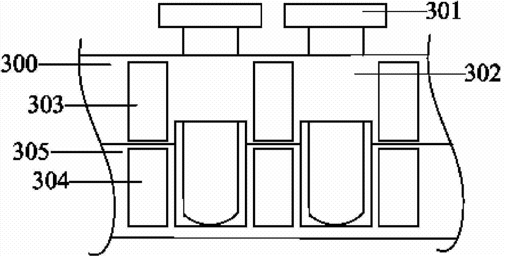
[0068] Please refer to Figure 8 , based on the test tube rack displacement detection method provided in Embodiment 2, this embodiment provides a device for detecting the test tube rack displacement of the analyzer assembly line. In a specific example, the device for detecting the test tube rack displacement includes features A voltage acquisition module 601 and a shift judgment module 602 .

[0069] The characteristic voltage acquisition module 601 is used to obtain the detection signal output by the sensor during a single shift of the test tube rack, and obtain the end voltage at the end of the test tube rack shift and the maximum value between the initial shift and the end of the shift from the detection signal Voltage.

[0070] The shift judging module 602 is used to judge whether the ratio of the maximum voltage to the end voltage satisfies the first judging condition. If so, it is judged that the test tube rack is shifted correctly; otherwise, it is judged that the test...


PUM


Abstract

A test tube stand for an analyzer pipeline. The test tube stand (201) is provided with multiple test tube positions for accommodating test tubes (203). One side of the test tube stand (201) is provided with a lighting preventing plate (300) traversing multiple test tube positions. A second characteristic region (303) is disposed between every two neighboring test tube positions on the lighting preventing plate (300). A first characteristic region (302) is disposed between every two second characteristic regions (303). A preset step level difference exists between the first characteristic region (302) and the second characteristic region (303).

Description

technical field [0001] The application relates to an analyzer assembly line system, a test tube rack, a displacement detection method and a device thereof. Background technique [0002] On the blood cell analysis line, the test tube rack is loaded with test tubes (containing blood samples) from the loading platform along the track to the detection area of ​​the blood cell analyzer, and then moves one test tube position at a time so that the test tubes pass through the test tube presence or absence detection sensor one by one And the sampling needle, the number is detected by the analyzer and the sample is collected. Since the test tube rack can hold multiple samples, if the test tube rack does not move in place (that is, the test tube does not move to the predetermined position) due to some factors, such as the loss of the motor, it may cause the remaining samples to be incorrectly numbered and sampled. Eventually, the test results and the identity of the tested person will...

Claims


Application Information

Patent Timeline
IPC IPC(8): B01L9/06G01D21/00G01N33/48
CPCB01L9/06G01N33/48G01D21/00A61B8/483A61B8/5246A61B8/4427A61B8/4461A61B8/0825A61B8/5269A61B8/13A61B8/14A61B8/4245A61B8/52A61B8/5215A61B8/523A61B8/5292A61B8/54G01N35/00594G01N35/021G01N2035/0413
Inventor 杜贤算胡力坚
Owner SHENZHEN MINDRAY BIO MEDICAL ELECTRONICS CO LTD
Why Eureka
Try Eureka