Buffer device for preventing yarn breakage, doffer and working method thereof
A buffer device and working method technology, applied in the direction of textiles and papermaking, etc., can solve the problems of increasing wiring workload, reducing efficiency, affecting production, etc., and achieve the effect of improving head retention rate, improving operating efficiency and improving production efficiency
- Summary
- Abstract
- Description
- Claims
- Application Information
AI Technical Summary
Problems solved by technology
Method used
Image
Examples
Embodiment 1
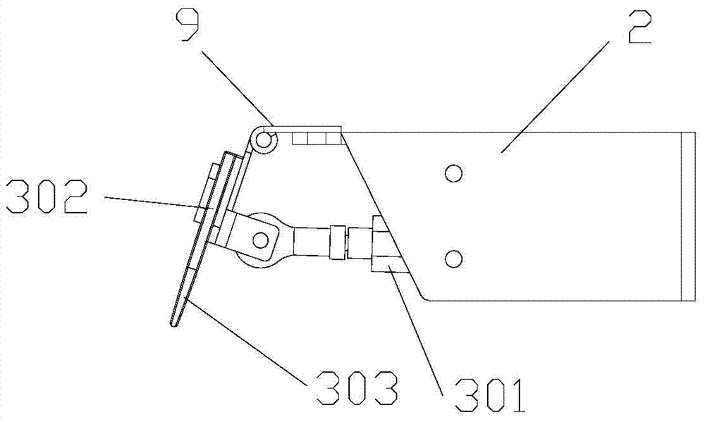
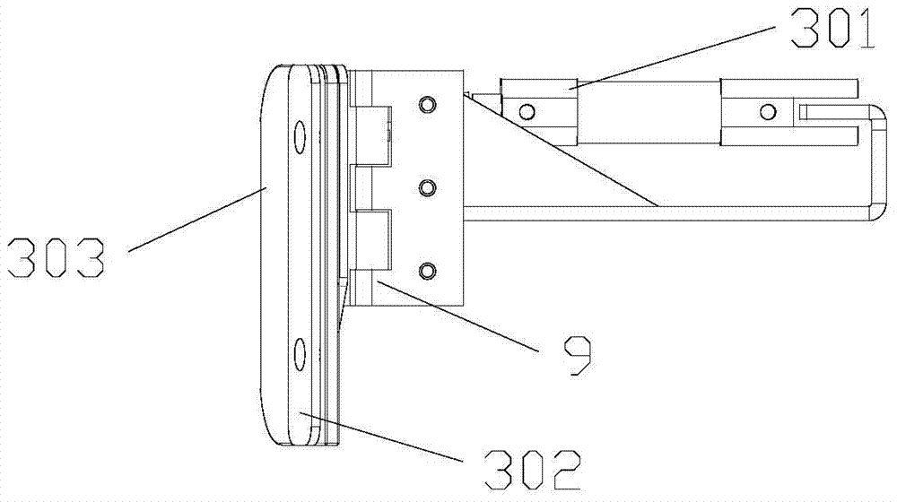
[0032] Such as figure 1 with figure 2 As shown, a buffer device for preventing yarn breakage of the present invention includes a power device 301, a fixing member 302 and an elastic member 303, the output shaft of the power device 301 is fixedly connected to the fixing member 302, and the power device 301 drives and fixes The part 302 swings, and one end of the fixed part 302 is fixedly connected with the elastic part 303 .
[0033] When installing the buffer device with the above structure, the fixed part 302 in the buffer device is movably connected to the moving frame 2 of the doffing machine through the movable part 9 . The movable part 9 can be a bearing, a hinge, a spring hinge, a torsion spring, a sliding brace or a gas spring. The fixed part 302 can rotate around the movable part. The whole buffer device moves with the moving frame 2 .
[0034] In the buffer device with the above structure, the power device 301 is used to periodically drive the fixing part 302 and...
Embodiment 2
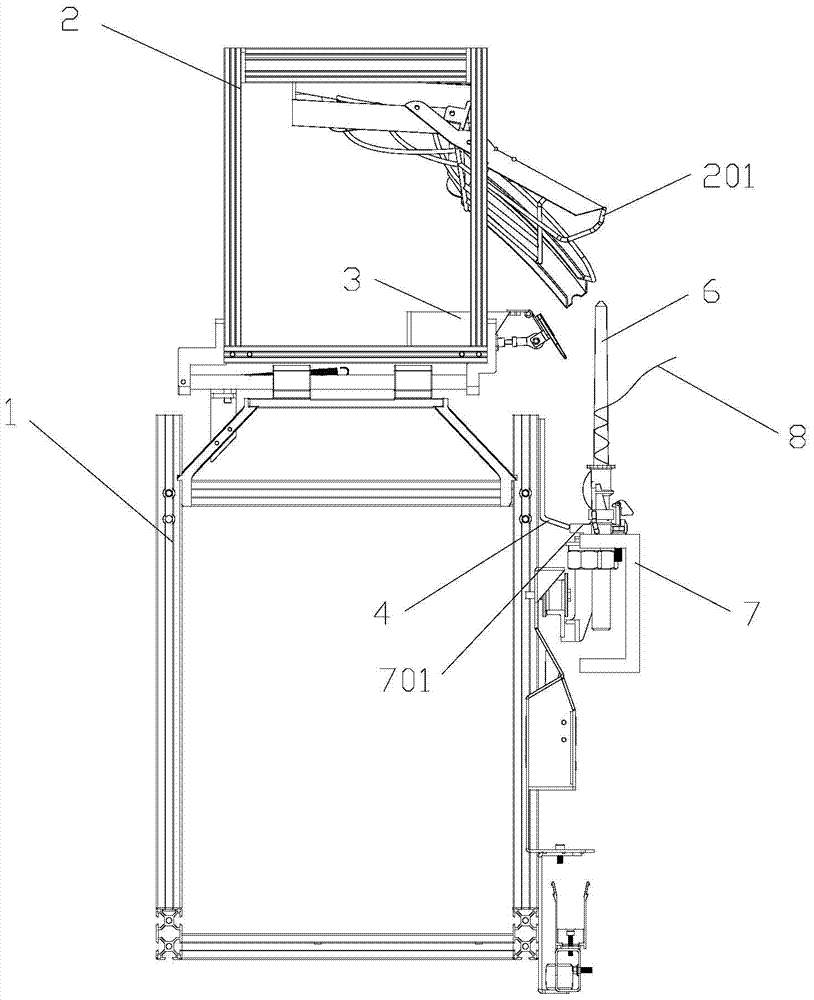
[0040] Such as image 3 with Figure 4 As shown, a doffer, the doffer includes a doffer body 1, a moving frame 2 and a buffer device 3, the moving frame 2 is slidably connected to the doffer body 1, and the moving frame 2 is provided with a pipe discharge channel 201. The buffer device 3 is connected on the mobile frame 2 . As a preferred solution, the buffer device 3 includes a power device 301 , a fixing part 302 and an elastic part 303 . The power device 301 is connected to the moving frame 2 , one end of the fixing member 302 is fixedly connected to the elastic member 303 , and the other end of the fixing member 302 is movably connected to the moving frame 2 . The output shaft of the power device 301 is fixedly connected with the fixing part 302, and the power device 301 drives the fixing part 302 to swing. Figure 4 In , the direction of the arrow is the forward direction of the doffer. Figure 5 The forward direction of the middle doffing machine and Figure 4 same...
Embodiment 3
[0051] A working method of a doffer, comprising the following steps:
[0052] Step 10): start the doffing machine, use the bobbin grabber of the doffer to pull the full yarn bobbin from the spindle bar of the spinning frame, then discharge the empty bobbin 5 from the pipe discharge channel 201 of the moving frame, and insert it into the spindle On the rod 6; during the falling process of the empty bobbin 5, utilize the buffer device 3 connected to the moving frame 2 to buffer the empty bobbin 5, reduce the falling speed of the empty bobbin 5, and the empty bobbin 5 falls to the bottom of the spindle bar; until The doffing frame moves to the end of spinning frame 7 to complete the work of catching full bobbins and inserting empty bobbins.
[0053] In the above method, the buffer device 3 adopted comprises a power unit 301, a fixed part 302 and an elastic part 303, the power unit 301 is connected on the moving frame 2, one end of the fixed part 302 is fixedly connected with the ...
PUM
 Abstract
Description
Claims
Application Information
 - R&D
- Intellectual Property
- Life Sciences
- Materials
- Tech Scout
- Unparalleled Data Quality
- Higher Quality Content
- 60% Fewer Hallucinations
Browse by: Latest US Patents, China's latest patents, Technical Efficacy Thesaurus, Application Domain, Technology Topic, Popular Technical Reports.
© 2025 PatSnap. All rights reserved.Legal|Privacy policy|Modern Slavery Act Transparency Statement|Sitemap|About US| Contact US: help@patsnap.com


