Beam through type corrugated steel plate energy consumption shear wall structure

A technology of corrugated steel plates and shear walls, applied to walls, building components, building structures, etc., can solve the problems of low assembly level, poor shear bearing capacity, self-heavyness, etc., so as to improve shear bearing capacity and improve Shock-absorbing ability, light weight effect

Active Publication Date: 2015-07-01
TONGJI UNIV
View PDF6 Cites 17 Cited by
  • Summary
  • Abstract
  • Description
  • Claims
  • Application Information

AI Technical Summary

Problems solved by technology

However, most of the energy-dissipating and shock-absorbing shear walls in the past are reinforced concrete shear walls or ordinary steel plate shear walls, which have shortcomings such as self-heavy weight, more consumables, low degree of assembly, and poor shear bearing capacity.

Method used


Image

  • Beam through type corrugated steel plate energy consumption shear wall structure
  • Beam through type corrugated steel plate energy consumption shear wall structure
  • Beam through type corrugated steel plate energy consumption shear wall structure

Examples


Embodiment 1

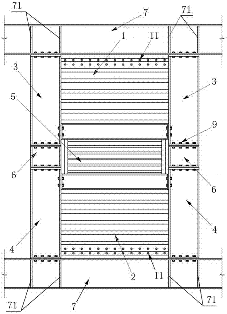
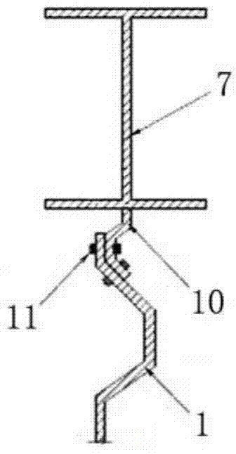
[0048] Such as figure 1 As shown, a beam-through corrugated steel plate energy-dissipating shear wall structure includes a first corrugated steel plate shear wall panel 1, a second corrugated steel plate shear wall panel 2, an upper edge steel column 3, and a lower edge steel column 4. The corrugated steel plate energy dissipation section 5 and the short steel columns 6 on the left and right sides of the corrugated steel plate energy consumption section; the corrugated steel plate energy dissipation section 5 and the short steel columns 6 on the left and right sides of the corrugated steel plate energy consumption section are located in the middle of the floor.

[0049]The upper end of the corrugated steel plate energy dissipation section 5 and the lower end of the first corrugated steel plate shear wall sheet 1 are connected together by welding or bolt connection or a combination of bolt connection and welding. The corrugated steel plate energy dissipation section 5 The lower...

Embodiment 2

[0059] The structural form of this embodiment is basically the same as that of Embodiment 1, and the difference with Embodiment 1 is:

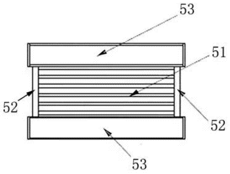
[0060] Such as Image 6 As shown, the corrugated steel plate energy dissipation section 5 includes a shear damper 54, and the left and right sides of the shear damper 54 are respectively welded with end plates or H-shaped steel columns 52, and the shear damper The device 51 and the end plate or the upper and lower ends of the H-shaped steel column 52 are respectively connected with a steel beam 53 by welding or bolt connection or a combination of bolt connection and welding. In this embodiment, the corrugated steel plate 51 of the corrugated steel plate energy dissipation section 5 in the first embodiment is replaced with a shear type damper 54, which can also achieve the purpose of energy dissipation.

[0061] To sum up, the energy-dissipating shear wall structure of the beam through corrugated steel plate of the present invention adopts the...


PUM


Abstract

The invention provides a beam through type corrugated steel plate energy consumption shear wall structure which comprises a first corrugated steel plate shear wall piece, a second corrugated steel plate shear wall piece, an upper edge steel column, a lower edge steel column, a corrugated steel plate energy consumption section and short steel columns on the left side and the right side of the corrugated steel plate energy consumption section. The corrugated steel plate energy consumption section and the short steel columns are located in the middle of a floor. The upper end and the lower end of the corrugated steel plate energy consumption section are connected with the first corrugated steel plate shear wall piece and the second corrugated steel plate shear wall piece respectively. The first corrugated steel plate shear wall piece and the second corrugated steel plate shear wall piece are connected with a floor beam through bolts respectively. The lower end of the upper edge steel column is connected with the upper ends of the short steel columns through bolts, and the upper end of the lower edge steel column is connected with the lower ends of the short steel columns through bolts. The upper end of the upper edge steel column and the lower end of the lower edge steel column are connected with the floor beam through bolts respectively. The first corrugated steel plate shear wall piece and the second corrugated steel plate shear wall piece are connected with the upper edge steel column and the lower edge steel column respectively. The corrugated steel plate shear wall pieces are adopted as a body of the shear wall structure, and therefore a building is small in dead weight, the material consumption is low, and the shear capacity of a wall body is improved.

Description

technical field [0001] The invention relates to the technical field of construction engineering, in particular to a beam-through corrugated steel plate energy-dissipating shear wall structure. Background technique [0002] The shear wall mainly bears the horizontal load caused by wind load or earthquake in the house, and prevents the structure from shearing damage. Passive control of structural shock absorption is an effective means of resisting earthquakes in the field of civil engineering in recent years. Based on the concept of structural control, it breaks through the traditional anti-seismic method that relies on the ductility of the structure itself to consume seismic energy. The energy dissipation control device can be used to consume seismic energy, reduce or even eliminate the damage of the main structure, and can significantly improve the seismic performance of the shear wall structure. Based on this, scholars at home and abroad have applied the concept of structu...

Claims


Application Information

Patent Timeline
Patent Type & Authority Applications(China)
IPC IPC(8): E04B2/58E04B1/98
Inventor 孙飞飞侯玉芳
Owner TONGJI UNIV
Why Eureka
Try Eureka