Driving control circuit used for laser tracker precision servo system

A technology for driving control circuits and laser trackers, applied in the field of laser trackers, can solve problems such as low reliability of collected data, poor low-speed control performance, and low control frequency, so as to reduce the amount of calculation, increase control frequency, and high operating efficiency Effect

Inactive Publication Date: 2015-07-01
ACAD OF OPTO ELECTRONICS CHINESE ACAD OF SCI
View PDF5 Cites 22 Cited by
  • Summary
  • Abstract
  • Description
  • Claims
  • Application Information

AI Technical Summary

Problems solved by technology

[0006] (1) Affected by hardware and control algorithm, the control frequency is low, and the low-speed control performance is poor;
[0007] (2) The reliability of the collected data is low;
[0008] (3) The circuit structure is relatively simple, the function is relatively single, and the flexibility is poor

Method used


Image

  • Driving control circuit used for laser tracker precision servo system
  • Driving control circuit used for laser tracker precision servo system
  • Driving control circuit used for laser tracker precision servo system

Examples


Embodiment Construction

[0028] Compared with the previous hardware circuit of the control system, the present invention adds FPGA chips and large-capacity SRAM chips with high cost performance, greatly improves the operating efficiency of the control algorithm, and the real-time performance of data collection. , and adopt the form of multi-board combination, which greatly increases the functionality and flexibility of the drive control circuit. In order to make the object, technical solution and advantages of the present invention clearer, the present invention will be described in further detail below in conjunction with specific embodiments and with reference to the accompanying drawings.

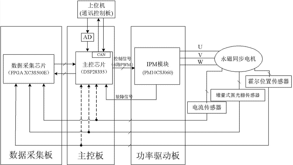
[0029] In one embodiment of the present invention, a drive control circuit for a precision servo system of a laser tracker is provided for driving and controlling a high-performance permanent magnet synchronous motor.

[0030] figure 1 It is a structural schematic diagram of the drive control circuit used in th...


PUM


Abstract

The invention provides a driving control circuit used for a laser tracker precision servo system. The driving control circuit comprises a data collection board used for collecting data of a permanent magnetic synchronous motor, a main control board connected with an upper computer and the data collection board and used for acquiring a target state command and reference input signals from the upper computer, acquiring data of the permanent magnetic synchronous motor from the data collection board and processing the target state command, the reference input signals and the data of the permanent magnetic synchronous motor to generate a control signal and a power driving board connected with the main control board and used for conducting power amplifying on the control signal output by the main control board and outputting a control voltage signal to drive the permanent magnetic synchronous motor to work. The circuit is formed by combining three circuit boards of the main control board, the data collection board and the power driving board in terms of hardware, configuration can be conducted according to the specific application requirements, and the flexibility is higher.

Description

technical field [0001] The invention relates to the technical field of laser trackers, in particular to a drive control circuit for a precision servo system of a laser tracker. Background technique [0002] The laser tracker has the characteristics of large measurement range, high precision, good dynamic performance, and real-time on-site measurement. It has been widely used in high-end intelligent manufacturing industries such as aerospace, rail transit, and shipbuilding. It can not only carry out high-precision three-dimensional measurement of space static objects, but also carry out tracking and measurement of moving objects. [0003] Building a high-performance precision servo system is the basis for the laser tracker to achieve tracking and precision measurement. As the core component of the precision servo system, the drive control circuit is designed to directly affect the control accuracy and tracking performance of the servo system. It is generally composed of sign...

Claims


Application Information

Patent Timeline
Patent Type & Authority Applications(China)
IPC IPC(8): G05B19/042
CPCG05B19/0428G05B2219/2656
Inventor 林心龙董登峰周维虎刘鑫张滋黎劳达宝纪荣祎
Owner ACAD OF OPTO ELECTRONICS CHINESE ACAD OF SCI
Why Eureka
Try Eureka