Submersible permanent magnet synchronous motor

A permanent magnet synchronous motor and submersible technology, which is applied to synchronous motors, magnetic circuits and electrical components with static armatures and rotating magnets. and other problems, to achieve the effect of improving assembly process, improving motor performance, and optimizing electromagnetic scheme

Inactive Publication Date: 2015-07-01
HANGZHOU SES MACHINERY
View PDF5 Cites 7 Cited by
  • Summary
  • Abstract
  • Description
  • Claims
  • Application Information

AI Technical Summary

Problems solved by technology

[0003] First, when the asynchronous motor is matched with a centrifugal pump, because the motor speed is lower than the synchronous speed, the motor efficiency and power factor are low;
[0004] Second, when the asynchronous motor is matched with the screw pump, because the motor speed is too high, it is difficult to reduce the speed to the required range of the screw pump through the reducer. Even if the reducer is used, the oil production cost will be greatly increased, and the oil recovery will also be reduced. Efficiency, and directly affects the life of the system;
[0005] The third is that asynchronous motors usually use frequency conversion control. When the AC power on the ground is transmitted to the underground for a long distance, the energy loss is serious, which greatly reduces the motor control accuracy, thereby reducing the system efficiency.
The number of poles of the motor rotor and the number of slots of the stator are too large, which will greatly increase the manufacturing cost. At the same time, it is not an optimal solution from the perspective of the electromagnetic scheme of the motor.
Moreover, the downhole sealing problem and the motor heat dissipation problem are not considered

Method used


Image

  • Submersible permanent magnet synchronous motor
  • Submersible permanent magnet synchronous motor
  • Submersible permanent magnet synchronous motor

Examples


Embodiment Construction

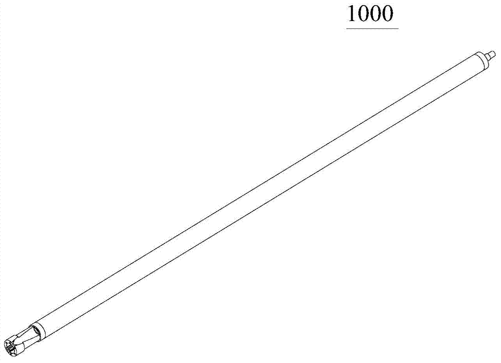
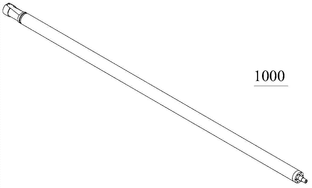
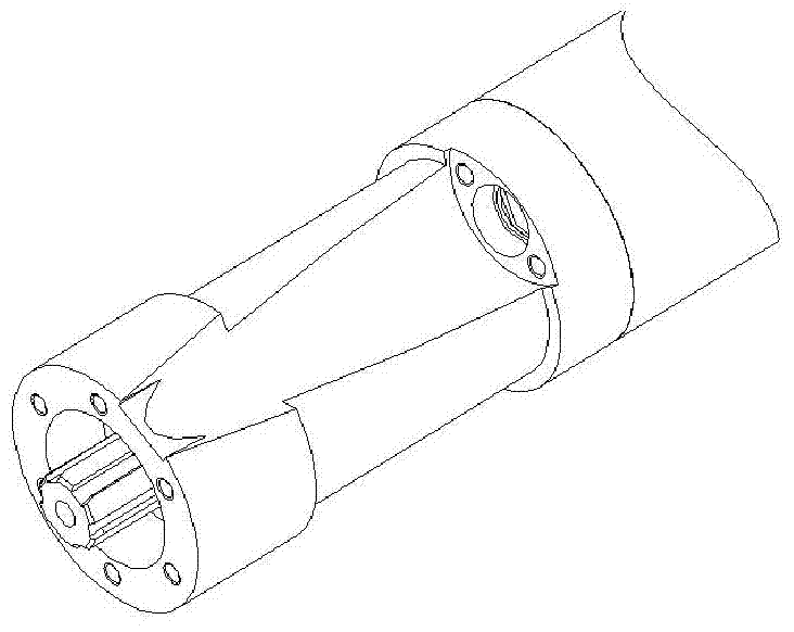
[0064] figure 1 It is one of the overall structural schematic diagrams of the oil submersible permanent magnet synchronous motor of the present invention. figure 2 It is the second schematic diagram of the overall structure of the oil submersible permanent magnet synchronous motor of the present invention. Figure 3a for figure 1 The enlarged view of the output end of the medium submersible permanent magnet synchronous motor, Figure 3b for figure 2 Enlarged view of the tail end of the medium submersible permanent magnet synchronous motor. Figure 3a , Figure 3b The two ends of the submersible permanent magnet synchronous motor are shown respectively. Such as Figure 1 to Figure 3b As shown, the present invention provides a kind of oil submersible permanent magnet synchronous motor 1000, this oil submersible permanent magnet synchronous motor is a modular design, its two ends are respectively provided with connecting devices, and one end is an output end connecting he...


PUM


Abstract

A submersible permanent magnet synchronous motor (1000) includes a motor casing, a stator and a rotor are correspondingly arranged in the motor casing, and two ends of the motor casing are respectively sealed and are connected to other external devices through connecting devices, such that an integrated-structure casing assembly (100) can be formed; the stator and the rotor are a stator assembly (200) and a rotor assembly (300) with multi-section type structures, respectively, the stator assembly (200) is fixed on the casing assembly (100), and the rotor assembly (300) is penetrated and arranged in the stator assembly (200); oil is injected into the casing assembly (100). By adopting the integrated-structure motor casing assembly, the stator assembly (200) and the rotor assembly (300) with multi-section type structures, the operation reliability and the performance of the motor are improved.

Description

technical field [0001] The invention relates to an oil submersible permanent magnet synchronous motor, which belongs to the technical field of mechanical manufacturing. Background technique [0002] At present, in my country and other oil-producing countries in the world, submersible motors are widely used in oil fields to drive electric submersible pumps to draw crude oil. The electric submersible pump system is an important equipment for oil field production. The power source of the traditional electric submersible pump system is mainly an asynchronous motor. The existing oil production system has the following problems in the supporting process of oil production: [0003] First, when the asynchronous motor is matched with a centrifugal pump, because the motor speed is lower than the synchronous speed, the motor efficiency and power factor are low; [0004] Second, when the asynchronous motor is matched with the screw pump, because the motor speed is too high, it is diffi...

Claims


Application Information

Patent Timeline
Patent Type & Authority Applications(China)
IPC IPC(8): H02K21/12H02K5/12H02K5/20H02K1/27H02K1/16
CPCH02K5/12H02K5/20H02K1/27H02K21/12H02K1/16H02K1/278H02K5/132
Inventor 郝双晖刘吉柱刘杰蔡一
Owner HANGZHOU SES MACHINERY
Why Eureka
Try Eureka