Improved zero-current converting H6 structural non-isolation photovoltaic grid-connected inverter and control method thereof

A zero-current, improved technology, applied in the field of non-isolated photovoltaic grid-connected inverters based on zero-current conversion H6 structure, can solve the problem that non-isolated photovoltaic grid-connected inverters cannot realize zero-current shutdown of the auxiliary switch tube and enter the grid Current and other issues, to achieve the effect of improving the power quality of the incoming grid, reducing leakage current, and improving the efficiency of the circuit

Inactive Publication Date: 2015-07-01
JIANGSU UNIV
View PDF4 Cites 6 Cited by
  • Summary
  • Abstract
  • Description
  • Claims
  • Application Information

AI Technical Summary

Problems solved by technology

For the second method, a zero-current switching H6 structure non-isolated photovoltaic grid-connected inverter proposed in this paper cannot realize the zero-current shutdown of the auxiliary switch tube and has the disadvantages of certain harmonics in the incoming grid current. A new topology and control method are proposed to reduce the leakage current and realize the zero-current turn-off of the auxiliary switch tube. At the same time, the free clamping of the freewheeling circuit during the freewheeling stage can make the common-mode voltage a constant value.

Method used


Image

  • Improved zero-current converting H6 structural non-isolation photovoltaic grid-connected inverter and control method thereof
  • Improved zero-current converting H6 structural non-isolation photovoltaic grid-connected inverter and control method thereof
  • Improved zero-current converting H6 structural non-isolation photovoltaic grid-connected inverter and control method thereof

Examples


Embodiment Construction

[0035] The specific implementation manner of the present invention will be further described below in conjunction with the accompanying drawings.

[0036] The present invention will improve from the following aspects to reduce the leakage current, reduce the switching loss and improve the working efficiency of the circuit. The specific content includes:

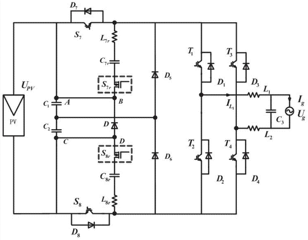
[0037] (1) In the topological structure, the auxiliary switch S 7r , S 8r Originally in the A-B, C-D branches, they are now moved to the position of the red box as shown in the figure to help the auxiliary switch tube achieve zero current shutdown during the freewheeling phase. The DC side is composed of two anti-parallel diodes The IGBT main switch S 7 , S 8 , resonant inductance L 7r , L 8r , resonant capacitor C 7r 、C 8r and two N-channel power MOSFETs with anti-parallel diodes removed 7r , S 8r composition, the resonant inductance L 7r , L 8r equal in size, both L r , C 7r 、C 8r equal in size, both C r ,T ...


PUM


Abstract

The invention discloses an improved zero-current converting H6 structural non-isolation photovoltaic grid-connected inverter and a control method thereof, and belongs to the field of electric power and electronics. The inverter is that a resonance inductor L7r and a resonance capacitor C7r are connected in series with a source electrode of an auxiliary switch tube S7r and then are connected in parallel with a main switching tube S7 according to the original zero-current converting H6 structural non-isolation photovoltaic grid-connected inverter; a resonance inductor L8r and a resonance capacitor C8r are connected in series with the source electrode of an auxiliary switch tube S8r and then are connected in parallel with the main switch tube S8; an anode of a diode D is connected with the source electrode of an MOSFET tube, and while a cathode of the diode D is connected with a drain electrode of the MOSFET; the auxiliary switches S7r and S8r are moved from AB and CD branches to be connected with the LC; the current of the auxiliary switch tubes can be automatically reduced to be zero through the LC unit in the inverter continuous flowing stage, thus the zero current on and off of the main and auxiliary switch tubes can be achieved; meanwhile, the modulating strategy is changed; the parameters of a filter is adjusted; the leakage electricity is reduced; the quality of electricity energy entering a power grid is improved; the working efficiency of the circuit can be increased.

Description

technical field [0001] The invention belongs to the technical field of photovoltaic grid-connected power generation technology and power electronics, and specifically relates to an improvement and working method of a non-isolated photovoltaic grid-connected inverter based on zero-current conversion H6 structure. Background technique [0002] Non-isolated photovoltaic grid-connected inverters are widely used in distributed photovoltaic power generation, not only can efficiently convert solar energy into electrical energy, but also can vigorously promote the development of the electric power industry with its light structure and simple method. There are two existing ways to reduce the leakage current: Method 1, based on the highest conversion efficiency circuit structure to improve the leakage current suppression performance. This method is to suppress the leakage current by improving the circuit topology and modulation strategy; the second method is to improve the circuit con...

Claims


Application Information

Patent Timeline
Patent Type & Authority Applications(China)
IPC IPC(8): H02M7/5387H02J3/38
CPCH02J3/383H02M7/5387Y02B70/10Y02E10/56
Inventor 廖志凌熊颖杰崔清华施卫东
Owner JIANGSU UNIV
Why Eureka
Try Eureka