Eccentric oscillation-type gear device

A gear device, eccentric swing technology, applied in the direction of gear transmission, transmission, transmission parts, etc., can solve the problems of bearing, gear damage, damage and so on

Inactive Publication Date: 2015-07-01
NABLESCO CORP
View PDF6 Cites 7 Cited by
  • Summary
  • Abstract
  • Description
  • Claims
  • Application Information

AI Technical Summary

Problems solved by technology

Sometimes these wear powders and foreign matter can cause damage to bear

Method used


Image

  • Eccentric oscillation-type gear device
  • Eccentric oscillation-type gear device
  • Eccentric oscillation-type gear device

Examples


Embodiment Construction

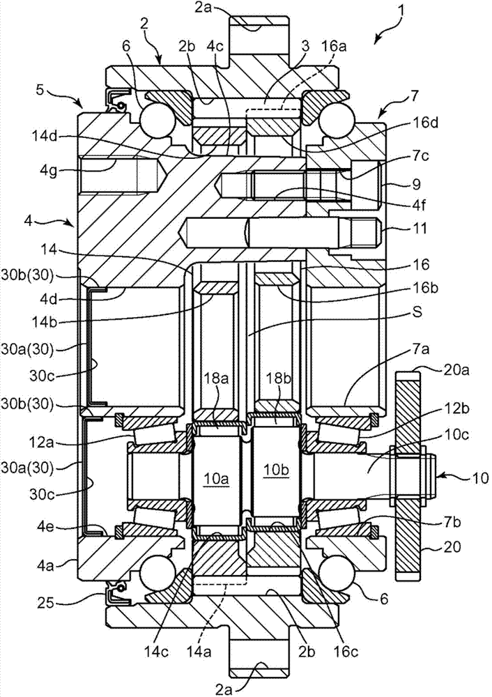
[0015] Hereinafter, embodiments for implementing the present invention will be described in detail with reference to the drawings. The eccentric oscillating gear unit (hereinafter, referred to as a gear unit) 1 of the present embodiment is used as a speed reducer in, for example, a rotary body of a robot, a rotary unit such as a wrist joint, and a rotary unit of various machine tools.

[0016] The gear unit 1 of the present embodiment is configured to obtain an output rotation decelerated from the input rotation by rotating the eccentric portions 10 a , 10 b of the crankshaft 10 to swing the swing gears 14 , 16 . Thereby, a relative rotation can be generated, for example, between the base of the robot (one cooperating member) and the revolving body (the other cooperating member). For example, a base is exemplified as a first member, and a revolving body is exemplified as a second member.

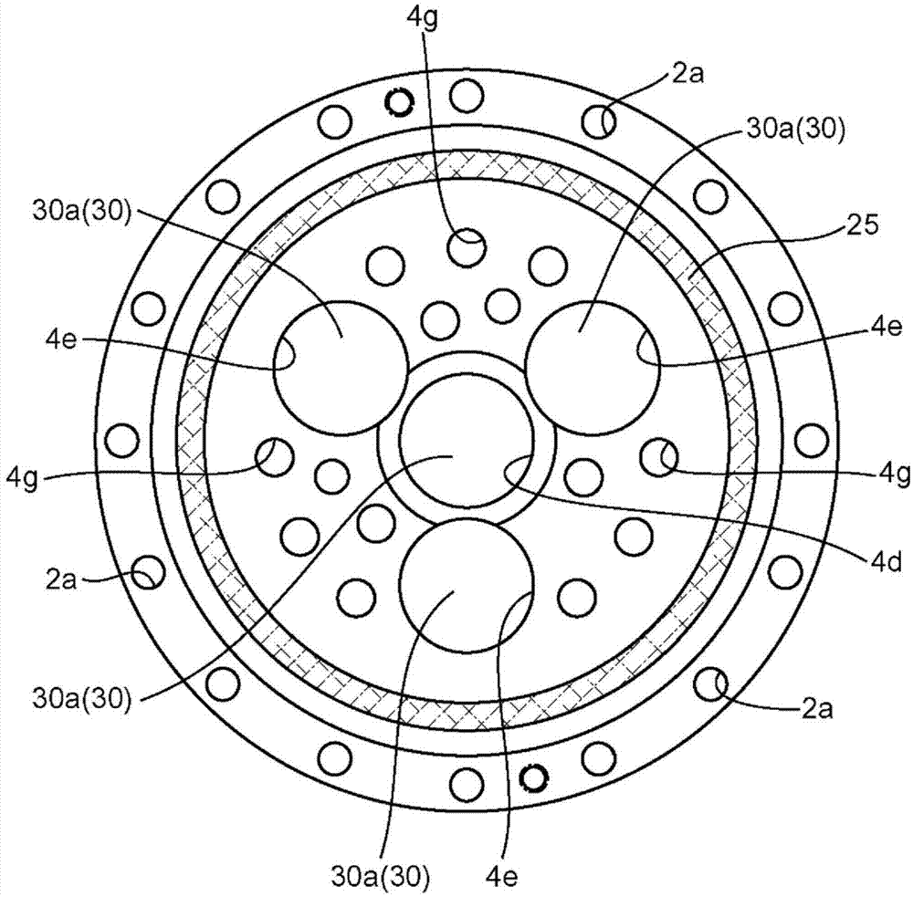
[0017] Such as figure 1 and 2 As shown, the gear device 1 includes an outer cylinder...


PUM


Abstract

An eccentric oscillation-type gear device (1) comprising: eccentric sections (10a, 10b); oscillating gears (14, 16); an outer tube (2) having an internal gear pin (3) that engages with the outer teeth (14a, 16a) of the oscillating gears (14, 16); a carrier (4); and an oil seal cap (30). A closed space (S) housing the oscillating gears (14, 16) is formed by the carrier (4) and the outer tube (2). A penetration hole (4d) and a crank shaft attachment hole (4e) that connect to the closed space (S) are formed in the carrier (4). The oil seal cap (30) is arranged on the penetration hole (4d) and the crank shaft attachment hole (4e), and has strong magnetism so as to be capable of attaching metal powder.

Description

technical field [0001] The present invention relates to an eccentric oscillating type gear unit. Background technique [0002] Conventionally, there is known an eccentric oscillating type gear device in which the rotational speed is reduced by a predetermined reduction ratio between two engagement members, as disclosed in the following reference document 1. The eccentric oscillating gear device includes: an outer cylinder fixed to one matching component; a gear frame arranged in the outer cylinder and fixed to the other matching component. The gear carrier has: a base plate part integrally formed with the shaft part; and an end plate part formed independently of the base plate part. A swing gear attached to the eccentric portion of the crankshaft is interposed between the base plate portion and the end plate portion, and in this state, the shaft portion and the end plate portion are fastened to each other with bolts. Then, when the swing gear rotates while being meshed wit...

Claims


Application Information

Patent Timeline
IPC IPC(8): F16H1/32F16H57/031
CPCF16H57/031F16H1/32F16H57/029F16H2001/323F16H57/0402
Inventor 古田和哉
Owner NABLESCO CORP
Why Eureka
Try Eureka