Milling vibration smashing type engineering grooving machine

A slotting machine and milling technology, which is applied in the field of milling, oscillating and smashing engineering slotting machines, can solve the time-consuming and labor-intensive process of connecting and dismantling the stroke drill pipe, the slotting machine cannot cut narrow grooves with a thickness, and the frictional resistance increases power. Consumption and other problems, to achieve the effect of saving engineering volume, convenient slag removal, and flexibility

Active Publication Date: 2015-07-08
项栋才
View PDF13 Cites 5 Cited by
  • Summary
  • Abstract
  • Description
  • Claims
  • Application Information

AI Technical Summary

Problems solved by technology

The inventor found in practical research that the stroke drill rods extending from the ground to the bottom of the groove in the above slotting machine are rigid double drill rods, which easily lead to uneven stress on the two rigid drill rods when excavating in uneven ground, and then breakage , buried drilling and other accidents, it is necessary to cancel the trip drill pipe to avoid this problem
At the same time, the above-mentioned slotting machine adopts a multi-drill structure, which not only requires multiple drills and corresponding sealing structures, but also needs a transfer case for driving multiple drills. At the same time, the frictional resistance of multiple drill seals also increases its power consumption.
[0004] In addition, among the related patents that the inventor has applied for before (such as the Chinese utility model patent of patent number CN99230153. Chinese invention patent with notification number CN101100865B) adopts a structure in which the reversing device is matched with the milling shaft, but the inventor found in subsequent practical applications that due to the large volume of the deceleration mechanism or the stroke drill rod, a large volume of The reversing device not only takes time and labor to connect and disassemble the stroke drill pipe, but also makes the whole slotting machine unable to dig narrow slots with small thickness, which limits the application range of the slotting machine

Method used


Image

  • Milling vibration smashing type engineering grooving machine
  • Milling vibration smashing type engineering grooving machine
  • Milling vibration smashing type engineering grooving machine

Examples


Embodiment 1

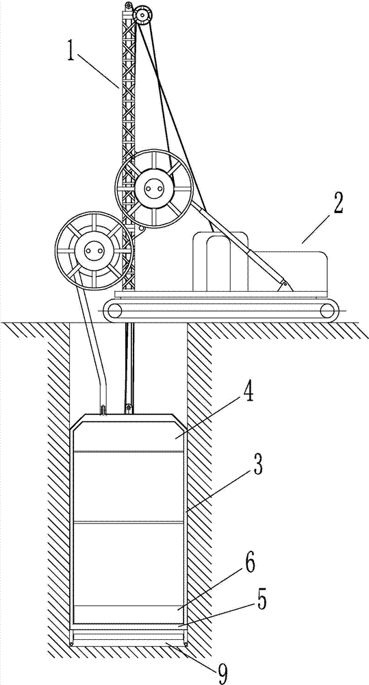
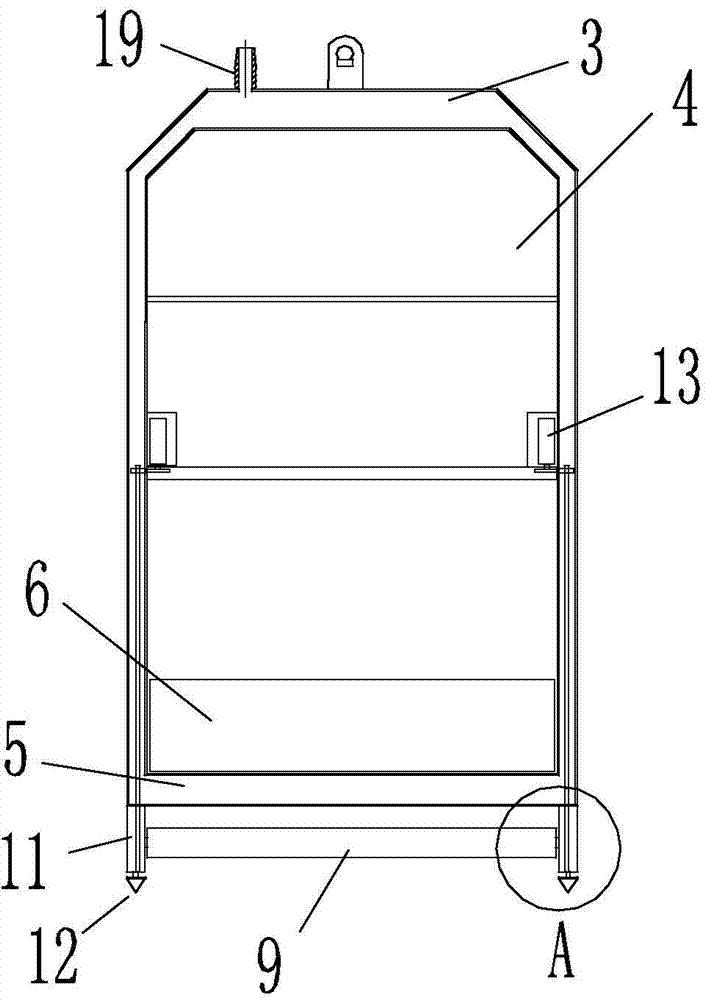
[0036] Such as Figure 1 to Figure 4 As shown, the milling and oscillating punching type engineering slotting machine of this embodiment includes a walking device 2 with a hoisting device 1 and a power system, and a monitoring device (not shown in the figure); the traction end of the hoisting device 1 is suspended with oscillation Impact milling device; the oscillating impact milling device includes a longitudinal guide frame 3, a rudder plate deviation correction device 4, a milling shaft 9 with a milling cutter, and a shock hammer 6; the rudder plate deviation correction device 4 is arranged in the guide frame 3, The milling shaft 9 is single and is arranged on the outside of the bottom beam 5 of the guide frame. The vibrating hammer 6 is located inside the bottom beam 5 of the guide frame and rises and falls on the upper end surface of the bottom beam 5; the axis of the milling shaft 9 is located in the plane of the guide frame 3, The milling shaft 9 is driven by a horizonta...

Embodiment 2

[0047] Such as Figure 5 As shown, compared with embodiment 1, the differences of this embodiment are as follows:

[0048] The milling shaft 9 is divided into two sections, and is arranged obliquely on both sides of the vertical transmission rod 21, and is driven by a vertical hydraulic motor 13 through a reversing device 22. The milling range of the milling shaft 9 covers the bottom end of the end column of the guide frame 3.

[0049] The reversing device 22 is a bevel gear. The hydraulic motor 10 is connected to the vertical transmission rod 21 through a spur gear. The vertical transmission rod 21 drives the milling shaft 9 through the bevel gear 22. The bottom of the vertical transmission rod 21 and the positioning drill bit 12 covering the bevel gear 22 connection.

Embodiment 3

[0051] Such as Image 6 As shown, compared with embodiment 1, the differences of this embodiment are as follows:

[0052] The milling axis 9 is segmented, including a horizontal milling axis 9-1, an inclined milling axis 9-2 located on both sides of the horizontal milling axis 9-1; the end milling range of the inclined milling axis 9-2 covers the bottom end of the end column of the guide frame 3.

[0053] A vertical hydraulic motor 13 is used, and the reversing device 25 is a bevel gear. The hydraulic motor 13 is connected to the vertical transmission rod 21 through a spur gear. The vertical transmission rod 21 drives the horizontal milling axis 9-1 and the inclined milling axis 9 through the bevel gear 25 -2. The bottom of the vertical transmission rod 21 is connected with the positioning bit 12 covered by the bevel gear. There are two sets of hydraulic motor 13, vertical transmission rod 21, and bevel gear reversing device 25.

[0054] The vertical transmission rod 21 passes throu...


PUM


Abstract

The invention relates to a milling vibration smashing type engineering grooving machine. The milling vibration smashing type engineering grooving machine comprises winch equipment, a power system, a walking device and a monitoring device. A vibration smashing milling device is suspended to the traction end of the winch equipment and comprises a longitudinal guiding frame, a rudder plate deviation correction device, a milling shaft with a milling cutter, and a vibration punch hammer. The axis of the milling shaft is located inside the plane where the guiding frame is located and the milling shaft is horizontally arranged and driven by a hydraulic motor. The milling shaft has the rotating milling state, and the external contour of the milling shaft eccentrically rotates when the milling shaft is in the rotating milling state. The hydraulic motor has the driving state and covers the rotating direction according to the preset period when in the driving state. The guiding frame is provided with a hydraulic oil pipeline communicated with the hydraulic motor. The suspension type frame is adopted for omitting a stroke drill rod, the milling shaft is adopted for replacing the multi-drill-bit structure, meanwhile, a reversing device is omitted or the size of the reversing device is decreased so that the size of a grooving machine tunneling device can be decreased, the grooving machine can cut narrow and deep grooves in various rock stratums, and the rudder plate deviation correction device is adopted for ensuring the grooving perpendicularity.

Description

Technical field [0001] The invention relates to a milling oscillating punching type engineering slotting machine, belonging to the technical field of slotting equipment. Background technique [0002] According to the inventor's understanding, in the engineering fields of water conservancy, transportation, construction, etc., it is necessary to build various underground continuous walls under different geological conditions. In the actual construction process, it is a very difficult problem to be solved if deep grooves are to be constructed in the stratum containing gravel, boulders, and floating rocks and in the harder rock formations. The slotting machine developed by the inventor can complete the slotting operation with high efficiency and low cost, and the effect is good. [0003] The Chinese invention patent (application number 201110273179.4, authorized announcement number CN102409972B) filed by the inventor on September 14, 2011 discloses a multi-bit rotary punching engineer...

Claims


Application Information

Patent Timeline
IPC IPC(8): E02F5/02E21B6/00
Inventor 刘农万泽仁
Owner 项栋才
Why Eureka
Try Eureka