Eureka AIR delivers breakthrough ideas for toughest innovation challenges, trusted by R&D personnel around the world.

Construction device and method for building foundation

A construction method and technology of construction devices, which are applied in construction, infrastructure engineering, earthwork drilling and other directions, can solve the problems of reduced work efficiency, increased cost, increased power consumption and damage rate, etc., and can improve the soil bearing capacity between piles, The effect of improving speed and ergonomics, and improving side friction resistance

Inactive Publication Date: 2015-07-08
王继忠
View PDF5 Cites 8 Cited by
  • Summary
  • Abstract
  • Description
  • Claims
  • Application Information

AI Technical Summary

Problems solved by technology

[0002] Among the current foundation treatment methods in our country, it is a common treatment method to form holes and make concrete piles by means of spiral drilling or drilling. The advantage is that the hole formation speed in soft soil foundations is relatively fast, but its disadvantages are, In the process of screw drilling, the soil in the pile hole is discharged to the outside of the ground, that is, the original soil is not well utilized, and additional labor and machinery are needed to clean and transport the discharged soil, resulting in reduced work efficiency, cost increase
At the same time, when a hole is formed by means of spiral pilot hole or drilling, when encountering a pile type with a large diameter, the corresponding drilling tool must be replaced, and the strength and motor power of the construction equipment are very high, and the power consumption The quantity and damage rate are significantly increased, so the construction cost is higher and the construction period is longer

Method used

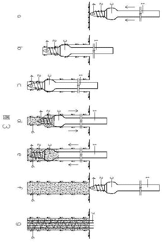

Image

  • Construction device and method for building foundation
  • Construction device and method for building foundation
  • Construction device and method for building foundation

Examples


Embodiment Construction

[0030] The present invention will be further described below in conjunction with the accompanying drawings.

[0031] figure 1 is a schematic diagram of an embodiment of the construction device of the present invention, as figure 1 As shown, the construction device includes a drill rod 1 and a drill bit 2, the lower end of the drill rod 1 is connected with a larger diameter expanding body 3, the lower end of the expanding body 3 is connected to the drill bit 2, the outer wall of the drill bit 2 is provided with helical blades, and the drill rod 1 The interior of the drill bit is a hollow pipe that can transport concrete, and the lower end of the hollow pipe communicates with the discharge port 4 arranged at the bottom of the drill bit 2 .

[0032] figure 2 is a schematic diagram of another embodiment of the construction device of the present invention, as figure 2 As shown, the construction device includes a drill rod 1 and a drill bit 2, the lower end of the drill rod 1 i...


PUM


Abstract

The invention provides a filing device for a building foundation, and provides a construction method through the device. The construction method has the advantages that the construction of hole forming, diameter expanding and concrete pressing and filling can be performed at a time; the diameter of a pile body can be increased while the original soil is utilized, so that the working efficiency is increased, and the cost is saved. The construction device comprises a drilling rod and a drill bit. The construction device is characterized in that the lower end of the drilling rod is connected with a diameter expanding body; the drill bit provided with spiral blades is connected to the lower end of the diameter expanding body; a hollow pipeline is arranged in the drilling rod and communicated with a discharging opening. The construction method comprises the steps of 1) aligning the drilling rod to a pile position; 2) rotating the drilling rod to synchronously rotate and drill the drill bit and the diameter expanding body, wherein the diameter of a pile hole can be expanded while the soil is extruded into the pile hole, and a backpressure is applied to in case of a hard soil layer; 3) continuing the operation of step 2) until reaching the design depth; 4) selecting one of the two modes to fill the concrete to the pile bottom; 5) continuing the operation of step 4) to form a concrete pile body; 6) reversely inserting a reinforcement cage in the concrete pile body, or paving a cushion layer on the surface of the pile top.

Description

technical field [0001] The invention relates to the field of civil engineering, in particular to the construction of piles. Background technique [0002] Among the current foundation treatment methods in our country, it is a common treatment method to form holes and make concrete piles by means of spiral drilling or drilling. The advantage is that the hole formation speed in soft soil foundations is relatively fast, but its disadvantages are, In the process of screw drilling, the soil in the pile hole is discharged to the outside of the ground, that is, the original soil is not well utilized, and additional labor and machinery are needed to clean and transport the discharged soil, resulting in reduced work efficiency, Higher costs. At the same time, when a hole is formed by means of spiral pilot hole or drilling, when encountering a pile type with a large diameter, the corresponding drilling tool must be replaced, and the strength and motor power of the construction equipme...

Claims


Application Information

Patent Timeline
IPC IPC(8): E21B10/32E21B17/00E02D15/04E02D5/36
Inventor 王继忠
Owner 王继忠
Why Eureka
Eureka Blog
Learn More