Vacuum thermal insulation house body used for ultralow temperature refrigeration house

A vacuum insulation and ultra-low temperature technology, which is applied in household refrigeration devices, applications, household appliances, etc., can solve the problems of condensation on the outer surface of the enclosure structure, increase the operating cost of the refrigeration system, and cannot produce the storage board. The thermal effect is obvious, the effect of solving condensation and bulky, and reducing mechanical damage

Inactive Publication Date: 2015-07-08
TIANJIN UNIV OF COMMERCE
View PDF10 Cites 5 Cited by
  • Summary
  • Abstract
  • Description
  • Claims
  • Application Information

AI Technical Summary

Problems solved by technology

[0003] Traditional cold storage boards use heat insulating materials such as rigid polyurethane boards. The general thermal conductivity is 0.024W / (m k). Satisfy the principle of no condensation on the surface and the heat flow per unit area is less than a certain value. At the same time, the existing process cannot produce a library board with sufficient thickness
[0004] At present, simply using the traditional storage plate structure will cause serious surface condensation on the outer surface of the enclosure structure, which will greatly increase the loss of cooling capacity and increase the operating cost of the refrigeration system

Method used


Image

  • Vacuum thermal insulation house body used for ultralow temperature refrigeration house
  • Vacuum thermal insulation house body used for ultralow temperature refrigeration house
  • Vacuum thermal insulation house body used for ultralow temperature refrigeration house

Examples


Embodiment Construction

[0026] The present invention will be described in further detail below in conjunction with the accompanying drawings and specific embodiments.

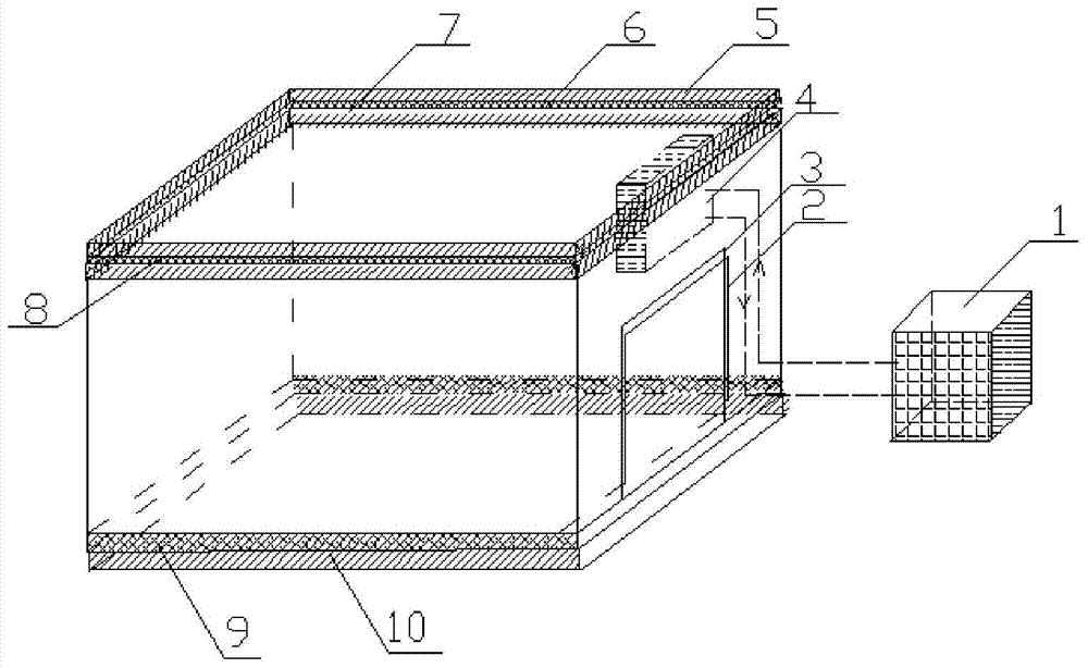
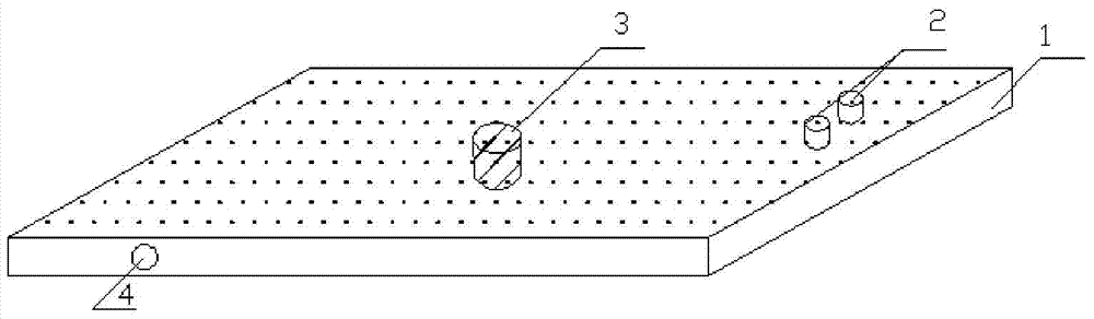
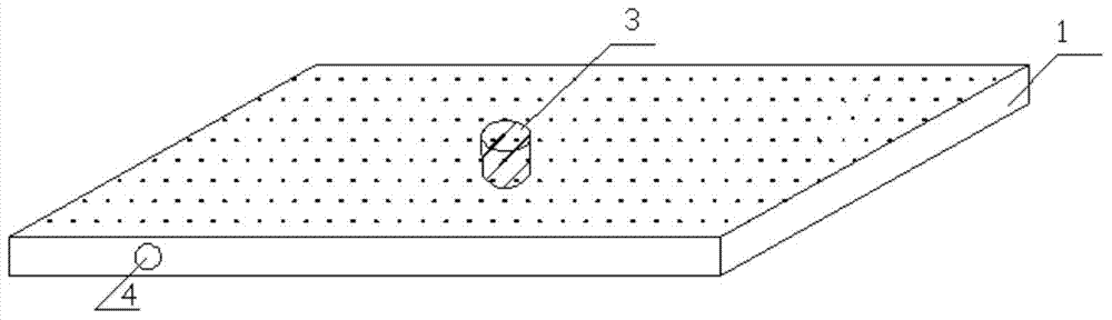
[0027] The schematic diagram of the vacuum heat insulation storage body used in the ultra-low temperature cold storage of the present invention is as follows figure 1 As shown, it consists of enclosure, top shelf and bottom shelf. The enclosure is made up of a front wall storage panel, a left enclosure storage panel, a right enclosure storage panel and a rear enclosure storage panel, and a storage door is installed on the front wall storage panel. The structure of the front panel, the left panel, the right panel and the rear panel is the same as that of the top panel, except that an evaporator installation hole is added on the top panel. The front panel, the left panel, the right panel, the rear panel and the top panel are respectively composed of an inner rigid polyurethane board 7, a middle stainless steel vacuum layer 6 and an out...


PUM


Abstract

The invention discloses a vacuum thermal insulation house body used for an ultralow temperature refrigeration house. The house body used for the ultralow temperature refrigeration house is constituted by a vacuum composite structure made of high-strength stainless steel so that the weight of a space enclosing structure can be reduced, the thermal insulation performance and the operation stability of a refrigeration system can be improved, and the operation cost of the refrigeration house can be reduced. The house body is composed of enclosing barriers, a top house plate and a bottom house plate, and the enclosing barriers are composed of a front house enclosing plate, a left house enclosing plate, a right house enclosing plate and a rear house enclosing plate. The front house enclosing plate, the left house enclosing plate, the right house enclosing plate, the rear house enclosing plate and the top house plate are each a composite house plate which is composed of inner layer rigid polyurethane plates, an intermediate stainless steel vacuum layer and outer layer rigid polyurethane plates, vacuuming holes are formed in each intermediate stainless steel vacuum layer, high-strength supporting insulating rods are arranged in each intermediate stainless steel vacuum layer, and the intermediate stainless steel vacuum layer and the inner layer rigid polyurethane plates of the top house plate are provided with air-cooled evaporator mounting holes; the bottom house plate is composed of thin-layer reinforced concrete slabs at the upper layer and rigid polyurethane plates at the lower layer.

Description

technical field [0001] The invention relates to an ultra-low temperature cold storage, in particular to a vacuum heat insulation storage body used for the ultra-low temperature cold storage. Background technique [0002] The ultra-low temperature cold storage is used in special occasions such as low-temperature medical treatment, low-temperature storage, and low-temperature test environment. The temperature difference between the inside and outside of the storage can reach more than 150°C. [0003] Traditional cold storage boards use heat insulating materials such as rigid polyurethane boards. The general thermal conductivity is 0.024W / (m k). Satisfy the principles of no condensation on the surface and less than a certain value of heat flow per unit area. At the same time, the existing process cannot produce a library board with sufficient thickness. [0004] At present, simply using the traditional storage plate structure will cause serious surface condensation on the oute...

Claims


Application Information

Patent Timeline
Patent Type & Authority Applications(China)
IPC IPC(8): F25D23/06
CPCF25D23/06F25D23/065
Inventor 刘斌王超董小勇
Owner TIANJIN UNIV OF COMMERCE
Why Eureka
Try Eureka