Linear frequency domain optical grating and design method thereof

A design method, grating technology, applied in the field of optics

Active Publication Date: 2015-07-08
武汉木兰金桥科技有限公司
View PDF4 Cites 3 Cited by
  • Summary
  • Abstract
  • Description
  • Claims
  • Application Information

AI Technical Summary

Problems solved by technology

Therefore, spectrometers made of traditional diffraction gratings or prisms can only be wavelength linear

Method used


Image

  • Linear frequency domain optical grating and design method thereof
  • Linear frequency domain optical grating and design method thereof
  • Linear frequency domain optical grating and design method thereof

Examples


Embodiment 1

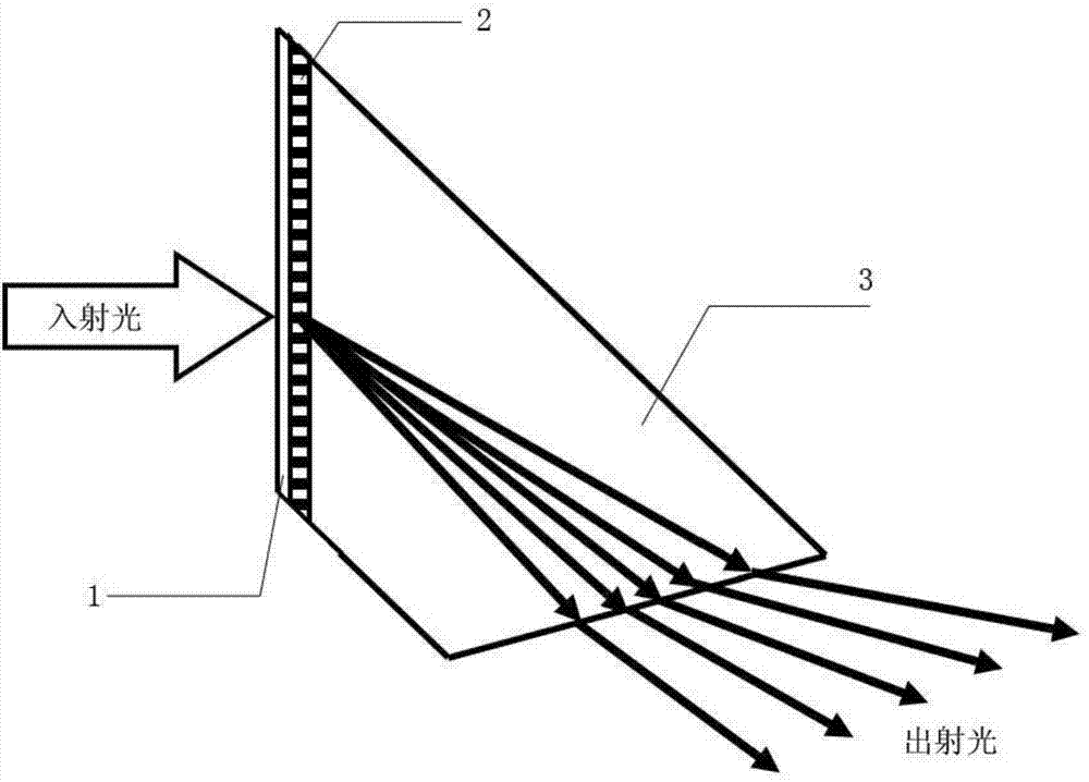
[0034] Such as figure 1 As shown, a design method of a linear frequency domain grating of the present invention includes attaching a diffractive medium to a prism to form a diffractive layer, and then covering with an optical glass protective layer; by

[0035] no 1 sinθ 1 =n 2 sinθ 2

[0036] Obtain the exit angle of the incident light after passing through the optical glass protective layer, where n 1 is the refractive index of the first medium, n 2 is the refractive index of the second medium, where the first medium can be air, and the second medium here is an optical glass protective layer, θ 1 is the incident angle of the incident light incident on the optical glass protective layer, θ 2 is the exit angle of the incident light after passing through the optical glass protective layer, θ 2 is also the incident angle when the incident light enters the diffractive layer; then by the grating equation:

[0037] λ·μ·m=sinθ 2 +sinθ 3

[0038] Obtain the diffraction ...


PUM


Abstract

The invention relates to the field of optics, in particular to a linear frequency domain optical grating and a design method thereof. The linear frequency domain optical grating comprises an optical glass protection layer, a diffraction layer and a prism. A diffraction medium is attached to the prism to form the diffraction layer. The diffraction layer is covered with the optical glass protection layer. A spectrum formed after incident light passes through the linear frequency domain optical grating to be scattered has frequency linearity. The linear frequency domain optical grating can be used for manufacturing a linear frequency domain spectrograph. The manufactured linear frequency domain spectrograph has the advantages of being small in size, light in weight, small in scattered device number and short in assembling and debugging time, light loss and light noise which are caused to the linear frequency domain optical grating due to interface reflection are effectively reduced, and meanwhile the manufacturing cost of the linear frequency domain optical grating is reduced. The linear frequency domain optical grating is widely applied to the modern spectroscopy fields such as optical imaging OCT, spectrum analysis and optical communication.

Description

technical field [0001] The invention relates to the field of optics, in particular to a linear frequency domain grating and a design method thereof. Background technique [0002] Existing diffraction gratings or prisms scatter light linearly in wavelength. The so-called scattering here is wavelength linear, which refers to the existing diffraction grating or prism. Due to the difference in the wavelength of the incident light, the exit angle of the exit light is also different, and there is a gap between the wavelength of the incident light and the exit angle of the exit light. linear relationship. Therefore, spectrometers made of traditional diffraction gratings or prisms can only be wavelength linear. At this time, there is a nonlinear relationship between the frequency of the incident light and the exit angle of the exit light. In many occasions, the scattering of light by optical devices is required to be linear in frequency, that is, after the incident light is scatt...

Claims


Application Information

Patent Timeline
IPC IPC(8): G02B5/18G02B5/04
CPCG02B5/1814
Inventor 胡志林
Owner 武汉木兰金桥科技有限公司
Why Eureka
Try Eureka