
Spin wave directional transmission waveguide structure

A technology of waveguide structure and directional transmission, which is applied in the direction of waveguide, waveguide-type devices, circuits, etc., to achieve the effect of enriching transmission characteristics, excellent transmission characteristics, and expanding possibilities

Inactive Publication Date: 2015-07-08
FUDAN UNIV
View PDF6 Cites 12 Cited by
  • Summary
  • Abstract
  • Description
  • Claims
  • Application Information

AI Technical Summary

Problems solved by technology

The high efficiency, selectivity, and orientation of these spin wave transmissions put forward high requirements for the design of the transmission structure in magnetic materials, and the existing spin wave transmission structures are difficult to meet this requirement

Method used


Image

  • Spin wave directional transmission waveguide structure
  • Spin wave directional transmission waveguide structure
  • Spin wave directional transmission waveguide structure

Examples


Embodiment Construction

[0029] The present invention will be described in detail below in conjunction with specific embodiments and drawings, but the present invention is not limited thereto.

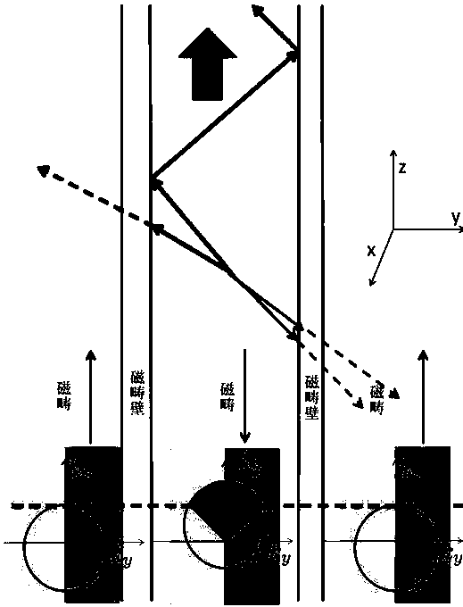
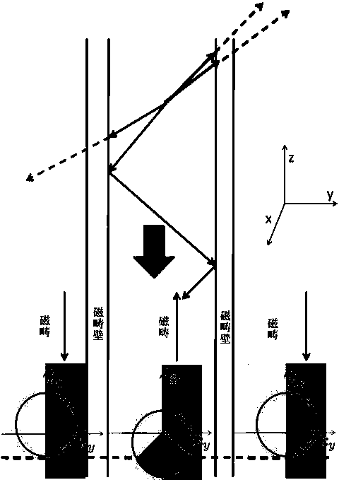
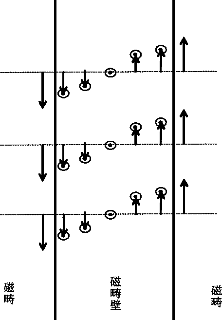
[0030] A spin wave unidirectional transmission waveguide structure in the present invention is composed of a two-dimensional thin film of magnetic material with DMI effect. Such as figure 1 , as shown in 2, the waveguide structure includes three adjacent magnetic domain regions, in which the magnetic direction of the middle magnetic domain is exactly opposite to that of the left and right magnetic domains, so the middle magnetic domain and the left and right magnetic domains respectively form a magnetic domain wall. The magnetic orientation in the three domains remains parallel to the direction in which the two domain walls are formed. The distribution of the magnetic orientation inside the left and right magnetic domain walls is as follows: image 3 , Figure 4 shown.

[0031] Under the DMI effect, when ...


PUM


Abstract

The invention belongs to the technical field of magnetic material signal transmission, in particular to a spin wave directional transmission waveguide structure. According to the waveguide structure, a magnetic structure is constructed on a two-dimensional film which is made of ferromagnetic insulating materials and has the DMI effect. The magnetic structure is composed of a plurality of magnetic domains pointing at the spin wave transmission direction and a magnetic domain wall of a special structure between the magnetic domains. The magnetization directions of the adjacent magnetic domains are opposite. Spin waves are transmitted through the total reflection mode, and the mode that the incident angle range needed for spin wave total reflection is changed through an externally-added electric field is adopted to change the spin wave transmission direction. The function of the structure is similar to the function of a publicly-known optical waveguide fiber, and the main difference is that the magnetic insulating materials serve as a medium of the structure, and the spin waves serve as a carrier of energy and information. According to the spin wave directional transmission waveguide structure, the spin waves can be transmitted in one direction or two directions according to needs, the transmission efficiency is high, attenuation is small, integration and expansion are easy, and the spin wave directional transmission waveguide structure can be combined with an existing electronic chip technology easily.

Description

technical field [0001] The invention belongs to the technical field of magnetic material signal transmission, in particular to a waveguide structure for directional transmission of spin waves in magnetic insulating materials, which is used for long-distance unidirectional transmission of spin waves in magnetic insulating materials. Background technique [0002] Spin wave refers to the excited state of magnetism in magnetic materials, and it widely exists in all magnetic materials. In magnetic insulating materials, since there are no conducting electrons, spin waves become a new type of carrier for transmitting information. It is easy to excite, easy to detect, high information storage density, low power consumption, easy coupling, and good integration with existing industrial technology. It is an ideal information carrier for the next generation of information technology following modern electronics and light as information carriers. [0003] The transmission of signals in ...

Claims


Application Information

Patent Timeline
IPC IPC(8): H01P3/12
Inventor 兰金余伟超肖江
Owner FUDAN UNIV
Learn More