Highly Modular Flat Multiphase Permanent Magnet Linear Motor

A permanent magnet linear motor, modular technology, applied in the direction of electromechanical devices, electrical components, electric components, etc., can solve the problems of high degree of electromagnetic coupling between phases, difficult modular design of motors, difficult fault isolation, etc., to achieve power density. Large, good magnetic isolation effect, low manufacturing and maintenance costs

Active Publication Date: 2019-12-10
HARBIN INST OF TECH
View PDF8 Cites 0 Cited by
  • Summary
  • Abstract
  • Description
  • Claims
  • Application Information

AI Technical Summary

Problems solved by technology

[0004] The purpose of the present invention is to solve the problem of difficulty in fault isolation when a fault such as winding short circuit occurs in a conventional multiphase permanent magnet linear motor, and the difficulty in modular design of the motor due to the high degree of electromagnetic coupling between phases, and provides a high-level module Flat-plate multi-phase permanent magnet linear motor

Method used


Image

  • Highly Modular Flat Multiphase Permanent Magnet Linear Motor
  • Highly Modular Flat Multiphase Permanent Magnet Linear Motor
  • Highly Modular Flat Multiphase Permanent Magnet Linear Motor

Examples


specific Embodiment approach 1

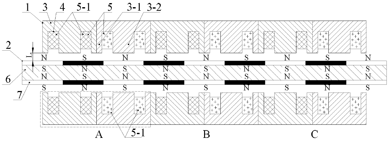
[0016] Specific implementation mode one: the following combination Figure 1 to Figure 3 Describe this embodiment, the highly modular flat-plate multiphase permanent magnet linear motor described in this embodiment includes k stators 1 and permanent magnet movers 2, k=1 or 2, when k=1, the stator 1 is set On one side of the permanent magnet mover 2; when k=2, two stators 1 are symmetrically arranged on both sides of the permanent magnet mover 2;

[0017] There is an air gap of length L between the stator 1 and the permanent magnet mover 2;

[0018] The stator 1 is assembled by 2m stator modules, m is the phase number of the motor, and the 2m stator modules are assembled in the axial direction to form a flat-shaped stator 1; each stator module includes a stator core 3 and a concentrated winding 5; the stator core Two fault-tolerant teeth 3-1 and one armature tooth 3-2 are arranged on 3, the armature tooth 3-2 is located between the two fault-tolerant teeth 3-1, and the length ...

specific Embodiment approach 2

[0023] Embodiment 2: This embodiment further explains Embodiment 1, m≥3, and the annular concentrated winding 5 is a concentrated winding of three phases or more.

[0024] The use of multi-phase windings can improve the fault-tolerant operation performance of the highly modular flat multi-phase permanent magnet linear motor.

specific Embodiment approach 3

[0025] Embodiment 3: In this embodiment, Embodiment 1 is further described. The stator core 3 is made of silicon steel sheet, amorphous ferromagnetic composite material or SMC soft magnetic composite material.

[0026] The mover core 6 is made of solid steel, silicon steel sheet, amorphous ferromagnetic composite material or SMC soft magnetic composite material.


PUM


Abstract

The invention belongs to the field of permanent magnet motors, and relates to a highly-modularized flat plate type multiphase permanent magnet linear motor. The problems that when a winding short circuit and other failures happen to a conventional multiphase permanent magnet linear motor, the failure isolation difficulty is large, and motor modular design difficulty is large due to the high interphase electromagnetic coupling degree are solved. The highly-modularized flat plate type multiphase permanent magnet linear motor comprises a stator and a permanent magnet rotor, the stator can be arranged on one or two sides of the permanent magnet rotor, and an air gap exists between the stator and the permanent magnet rotor. The stator is formed by assembling 2m stator modules. The stator modules are assembled to be in a flat plate shape in the axial direction. Each stator module comprises a stator iron core, an armature tooth, two fault-tolerant teeth and two concentrated windings. A one-phase module of the highly-modularized flat plate type multiphase permanent magnet linear motor is composed of two adjacent stator modules. The permanent magnet rotor is formed by assembling a permanent magnet and a rotor iron core, and the permanent magnet rotor can be of a surface-mounted structure or a Halbach structure or an axial magnetization structure and the like.

Description

technical field [0001] The invention relates to a modular multiphase permanent magnet fault-tolerant motor, which belongs to the field of permanent magnet motors. Background technique [0002] Urban rail transit technology mainly has two technical modes, one is to use a rotating motor plus a gearbox to drive the wheels, and the friction between the wheels and rails to drive the vehicle forward; the other is to use a linear motor drive system. Compared with the traditional rotary motor traction technology, the rail transit system based on the linear motor has better climbing ability, no reduction gear and other devices are needed, the design freedom of the bogie and the line is large, and the excavation section of the tunnel is small, which is especially suitable for alignment Cities with difficult site and station selection, complex hydrogeological conditions, and dense buildings along the route. Safety and reliability are of paramount importance for linear motor drive syst...

Claims


Application Information

Patent Timeline
Patent Type & Authority Patents(China)
IPC IPC(8): H02K41/02
Inventor 隋义郑萍于斌刘家琦赵白鸽
Owner HARBIN INST OF TECH
Why Eureka
Try Eureka