L-shaped split type composite busbar

A composite busbar and split-type technology, applied in the direction of output power conversion device, electrical components, AC power input conversion to DC power output, etc., can solve problems such as damage, device overheating, IGBT out of control, etc., to improve reliability, Reduce loop inductance, facilitate repair and maintenance

Active Publication Date: 2015-07-08
CRRC YONGJI ELECTRIC CO LTD
View PDF5 Cites 8 Cited by
  • Summary
  • Abstract
  • Description
  • Claims
  • Application Information

AI Technical Summary

Problems solved by technology

[0002] During the switching process of the power device of the high-power variable frequency power supply, due to the influence of the parasitic inductance on the DC bus between the DC energy storage capacitor and the IGBT device and the induc...

Method used


Image

  • L-shaped split type composite busbar
  • L-shaped split type composite busbar
  • L-shaped split type composite busbar

Examples


Embodiment Construction

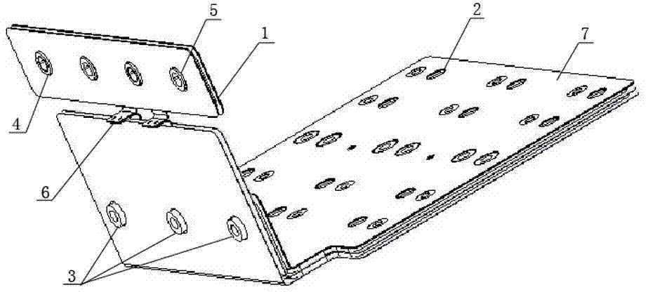
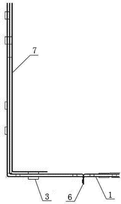
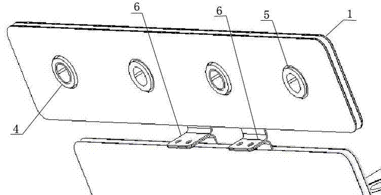
[0012] L-shaped split composite busbar, including the lower split composite busbar 7 composed of three layers of L-shaped busbars stacked in the same direction, the upper split composite busbar 1 composed of two layers of flat busbars stacked, and the adjacent busbars Insulating materials are filled between the rows, and the lower split composite busbar 7 is provided with an interface 2 for connecting circuit devices, and an AC output terminal 3 is drawn from one layer of the L-shaped busbar of the lower split composite busbar 7, One of the flat busbars of the upper split composite busbar 1 leads to the positive terminal 4 for inputting the forward DC voltage, and the other flat busbar of the upper split composite busbar 1 leads out to the output The negative terminal 5 of the negative DC voltage, the two-layer flat busbars of the upper split composite busbar 1 are respectively connected to the other two layers of L-shaped busbars of the lower split composite busbar 7 through l...


PUM


Abstract

The invention relates to the field of busbars in the electric technology, in particular to an L-shaped split type composite busbar which comprises a lower split composite busbar and an upper split composite busbar. The lower split composite busbar is formed by three layers of L-shaped busbars in an identical-direction-overlaying mode. The upper split composite busbar is formed by two layers of flat busbars in an overlaying mode. The position between two adjacent busbars is filled with insulation materials. A connector for being connected with a circuit device is arranged on the lower split composite busbar. An alternating output terminal is led out from one layer of L-shaped busbar of the lower split composite busbar. The L-shaped split type composite busbar replaces a direct-current bus, loop inductance is lowered, the reliability of IGBT working is improved, main circuit cable connecting is replaced, layout is easy, quality is reliable, the size and the weight of a system are reduced, and maintaining on a main circuit is convenient.

Description

technical field [0001] The invention relates to the field of bus bars in electrical technology, in particular to an L-shaped split composite bus bar. Background technique [0002] During the switching process of the power device of the high-power variable frequency power supply, due to the influence of the parasitic inductance on the DC bus between the DC energy storage capacitor and the IGBT device and the inductance of the IGBT module itself, a high peak voltage will be generated. This peak voltage, It will cause the device to overheat, and sometimes even cause the IGBT to lose control and exceed the rated safe working area of ​​the device and be damaged. [0003] Therefore, the peak voltage generated during the switching process must be limited within the allowable range, and one of the methods is to reduce the distributed inductance of the DC link power bus. Contents of the invention [0004] In order to solve the above technical problems, the present invention pr...

Claims


Application Information

Patent Timeline
IPC IPC(8): H02M7/00
Inventor 张晋芳马瑞朱杭杭杨春宇陈彦肖
Owner CRRC YONGJI ELECTRIC CO LTD
Why Eureka
Try Eureka