
Constant-tension installing winch for steel wire rope and cable

A constant tension, steel wire rope technology, applied in the field of marine engineering, can solve the problems of abandoned wire ropes or cables, unable to meet the tension requirements well, unstable tension, etc., and achieve the effect of reducing losses

Inactive Publication Date: 2015-07-15
PW SHANGHAI OFFSHORE
View PDF11 Cites 3 Cited by
  • Summary
  • Abstract
  • Description
  • Claims
  • Application Information

AI Technical Summary

Problems solved by technology

[0003] However, the existing methods lead to a series of problems: 1. To increase the tension by increasing the friction, the tension that can be provided is limited, and the tension requirements cannot be better met
2. During the operation, the wire rope or cable is easy to wear, and the friction force is unstable, resulting in unstable tension
3. If there is a gap in the wire rope or cable wound on the drum, the wire rope or cable on the outer layer is easily pulled into the gap at the bottom of the drum under the pull of the winch, causing serious wear and tear, and even causing the entire wire rope or cable to be discarded, resulting in huge loss
4. During the transmission process, the manual friction method cannot flexibly adjust the transmission power according to the actual situation. When it is necessary to reverse, it can only be reversed by manpower, and the steel wire rope or cable cannot be kept in tension during the reverse process, which will affect the progress of the project and exist. risk of rope

Method used


Image

  • Constant-tension installing winch for steel wire rope and cable

Examples


Embodiment Construction

[0011] The present invention will be described in detail below in conjunction with the accompanying drawings.

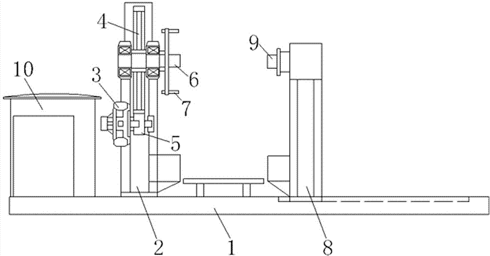
[0012] Such as figure 1 As shown, a constant tension installation winch for wire ropes and cables includes a base 1, a fixed bracket 2 fixedly connected to the base 1, a reduction gear transmission mechanism arranged on the fixed bracket 2, and the power of the reduction gear transmission mechanism The hydraulic motor 3 connected to the input end, the driving shaft 6 connected to the power output end of the reduction gear transmission mechanism arranged on the upper end of the fixed bracket 2 through the bearing, the fork device 7 arranged on the driving shaft 6, and the base 1 slide The cooperation of the rails can move left and right and is connected to the mobile bracket 8 on the base 1, the driven shaft 9 that is arranged on the upper end of the mobile bracket 8 through bearings facing the driving shaft 6, the hydraulic station that provides oil pressure for the ...


PUM


Abstract

The invention provides a constant-tension installing winch for a steel wire rope and a cable. The constant-tension installing winch comprises a base, a fixed support frame and a movable support frame, wherein the fixed support frame and the movable support frame are respectively arranged at the left half part and the right half part of the base, a speed reduction gear transmission mechanism, a hydraulic motor, a driving shaft and a shifting fork device are arranged on the fixed support frame, the hydraulic motor is connected with the power input end of the speed reduction gear transmission mechanism, the driving shaft is arranged at the upper end of the fixed support frame through a bearing and is connected with the power output end of the speed reduction gear transmission mechanism, the shifting fork device is arranged on the driving shaft, oil pressure of the hydraulic motor is provided by a hydraulic station, the upper end of the movable support frame and the driving shaft are provided with a driven shaft through a bearing in a mutually and directly facing way, the front end of the driving shaft is provided with a force sensor, and the force sensor and the hydraulic station are respectively and electrically connected with a hydraulic control system. The device has the advantages that the transmission power can be flexibly regulated according to actual conditions during rope winding cable distribution, the constant tension meeting the requirements can be provided, the rope locking and abrasion of the steel wire rope or the cable can be effectively avoided, the smooth proceeding of the work is ensured, and the service life of the steel wire rope is greatly prolonged.

Description

technical field [0001] The invention relates to the technical field of marine engineering, in particular to a constant tension installation winch for steel wire ropes and cables. Background technique [0002] In marine engineering and shipyards, rope spooling is often involved. In the process of winding and unwinding cables, it is necessary to maintain a certain tension on the steel wire rope or cable. In the prior art, a simple manual operation method is mostly used to increase the frictional force between the steel wire rope or cable and the reel, so as to maintain a certain tension. The transmission power is provided by the friction between the plank and the reel. [0003] However, the existing methods lead to a series of problems: 1. To increase the tension by increasing the friction force, the tension that can be provided is limited, and the tension requirement cannot be better met. 2. During the operation, the wire rope or cable is easy to wear and tear, and the fr...

Claims


Application Information

Patent Timeline
Patent Type & Authority Applications(China)
IPC IPC(8): B65H59/38
Inventor 郑永刚
Owner PW SHANGHAI OFFSHORE
Learn More