Magnetic bead driving method and apparatus allowing cells to do rectilinear motion in micro-fluidic chip

A technology of microfluidic chips and driving devices, applied in stress-stimulated microbial growth methods, biochemical equipment and methods, microorganisms, etc., to achieve the effects of avoiding magnetic field interference, maintaining activity, and wide application range

Active Publication Date: 2015-07-15
江苏大学扬州(江都)新能源汽车产业研究所
View PDF5 Cites 5 Cited by
  • Summary
  • Abstract
  • Description
  • Claims
  • Application Information

AI Technical Summary

Problems solved by technology

At present, the magnetic bead technology in microfluidics is mainly applied to the separation and fusion of cells by using permanent magnets or electromagnets. There is no mature device for the control of linear motion of cells.

Method used


Image

  • Magnetic bead driving method and apparatus allowing cells to do rectilinear motion in micro-fluidic chip
  • Magnetic bead driving method and apparatus allowing cells to do rectilinear motion in micro-fluidic chip
  • Magnetic bead driving method and apparatus allowing cells to do rectilinear motion in micro-fluidic chip

Examples


Embodiment Construction

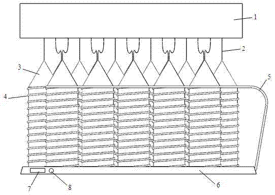
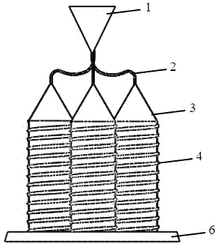
[0024] see figure 1 , 2 , 3, 4, the linear movement of cells in the microfluidic chip of the present invention of The lower part of the magnetic bead linear drive device is the base 6, and the upper part is the microfluidic flow channel 1. The microfluidic flow channel 1 is arranged in the left and right directions, and the magnetic beads combined with cells move from left to right or from left to right in the microfluidic flow channel 1. Right to left movement. A micro-magnetic pole array is installed between the base 6 and the microfluidic channel 1 .

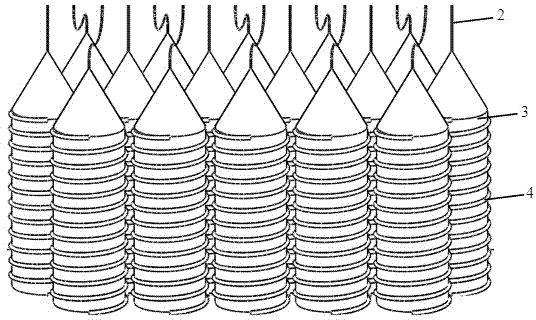
[0025] The micro-magnetic pole array is an array structure in which multiple micro-magnetic poles are arranged in front, middle and rear columns. Each micro-magnetic pole is composed of a magnetic needle 2, an electromagnet core 3 and a helical coil 4. In order to increase the Magnetic flux, the electromagnet core 3 is made of permalloy, a soft magnetic material with high magnetic permeability, and a helical coil 4 is wou...


PUM


Abstract

The invention discloses a magnetic bead driving method and apparatus allowing cells to do rectilinear motion in a micro-fluidic chip. According to the invention, the cross section of a micro-fluidic channel is an inverted isosceles triangle with a downward vertex; a micro magnetic pole array formed by a plurality of micro magnetic poles and composed of a front column, a middle column and a back column is arranged between a pedestal and the micro-fluidic channel; each micro magnetic pole is composed of a magnetic needle, an electromagnetic iron core and a spiral coil; the center of the top of each electromagnetic iron core is fixedly connected with the lower end of one magnetic needle, and the upper end of each magnetic needle is upwardly inserted into the micro-fluidic channel from the vertex of the inverted isosceles triangle all the upper ends of the magnetic needles inserted into the micro-fluidic channel are located in a same linear extending from left to right; and the on and off states of the spiral coils are optionally controlled via a one-chip microcomputer, so linear arraying, oriented movement and speed regulation of magnetic beads are realized. The magnetic bead driving method and apparatus are not influenced by properties like fluid concentration, a pH value and a dielectric constant, can prevent damage of cells and are beneficial for maintaining activity of cells.

Description

technical field [0001] The invention belongs to a microfluidic optical detection system, and relates to a device for controlling the motion of detected cells. The technology for controlling the motion of detected cells is one of the key elements determining the detection accuracy. A magnetic bead drive device for linear motion control of cells in a microchannel. Background technique [0002] To achieve high-sensitivity optical detection, the key is to reduce the influence of background light, especially excitation light, on the detection optical path. The area of ​​the excitation light spot directly depends on the stability and accuracy of the controlled movement of the detected cell flow. When the detected cells are completely moving along the same straight line, the excitation light spot can be focused to a small enough area to achieve ultra-high sensitivity and even single-cell detection. At present, the control technology for the linear movement of cells is mainly flow...

Claims


Application Information

Patent Timeline
Patent Type & Authority Applications(China)
IPC IPC(8): C12M1/42C12N13/00
Inventor 张荣标孙健任作为
Owner 江苏大学扬州(江都)新能源汽车产业研究所
Why Eureka
Try Eureka