
Acoustic power multi-stage amplification traveling-wave thermoacoustic engine system

A thermoacoustic engine and sound power technology, which is applied in the direction of hot gas variable capacity engine devices, machines/engines, mechanical equipment, etc., can solve the problem of complex output devices, unsuitable for driving a single high-power load, and unable to achieve multi-stage amplification of sound power. and centralized output, etc., to achieve the effect of simple output device, compact structure and high potential efficiency

Active Publication Date: 2015-07-15
TECHNICAL INST OF PHYSICS & CHEMISTRY - CHINESE ACAD OF SCI
View PDF6 Cites 10 Cited by
  • Summary
  • Abstract
  • Description
  • Claims
  • Application Information

AI Technical Summary

Problems solved by technology

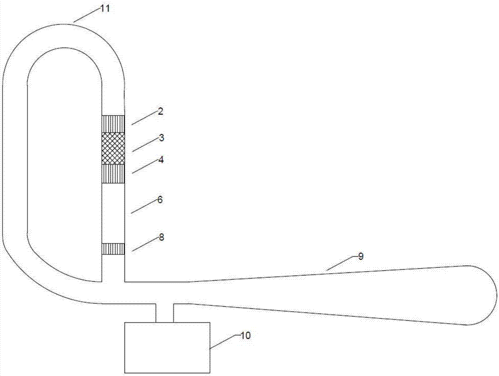
compared to figure 1 system, which greatly reduces the size of the resonant tube 9, and at the same time recovers the sound work dissipated in the resonant tube, greatly improving the power density and potential thermal efficiency of the system; at the same time, each regenerator 4 in the system is It is in the ideal traveling wave phase, which is beneficial to the conversion of sound power with higher efficiency; the high-temperature end-layer fluidization screen 5 and the low-temperature end-layer fluidization screen 7 are added at both ends of the thermal buffer tube 6, which is a good solution to the problem of thermoacoustic engines. The problem of cold and heat loss in the system; and, the system is equipped with a loop DC suppressor (DC suppressor 1 is installed at the connection between the inlet of each main cooler 2 and the resonance pipe to suppress the loop DC), eliminating the system Due to the changes in the above points, the performance of the system has been significantly improved; however, this system is mainly suitable for the output of sound power connected to multiple loads 10, the output device is complicated, and the output sound power of each unit is small, which cannot be realized Multi-stage amplification and concentrated output of sound power, not suitable for driving a single high-power load

Method used


Image

  • Acoustic power multi-stage amplification traveling-wave thermoacoustic engine system
  • Acoustic power multi-stage amplification traveling-wave thermoacoustic engine system
  • Acoustic power multi-stage amplification traveling-wave thermoacoustic engine system

Examples


Embodiment 1

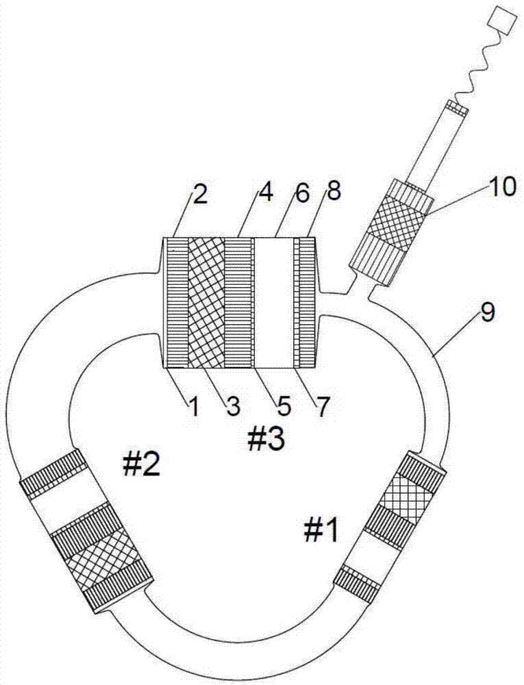
[0021] image 3 It is a schematic structural diagram of a traveling wave thermoacoustic engine driven pulse tube refrigerator system (embodiment 1) with multi-stage amplification of sound power of the present invention; image 3 As shown, the multi-stage sound power amplification traveling wave thermoacoustic engine system of the present embodiment 1 consists of 3 stages (#1 thermoacoustic engine unit, #2 thermoacoustic engine unit and #3 thermoacoustic engine unit) with equal length and cross-sectional area Different thermoacoustic engine units and loads are composed of 10; each level of thermoacoustic engine units is connected end-to-end through resonant tubes 9 with equal lengths and different cross-sectional areas to form a loop structure; each level of thermoacoustic engine units is connected in turn by DC suppressor 1, main cooler 2, regenerator 3, heater 4, high temperature end laminar fluidization element 5, thermal buffer tube 6, room temperature end laminar fluidizat...

Embodiment 2

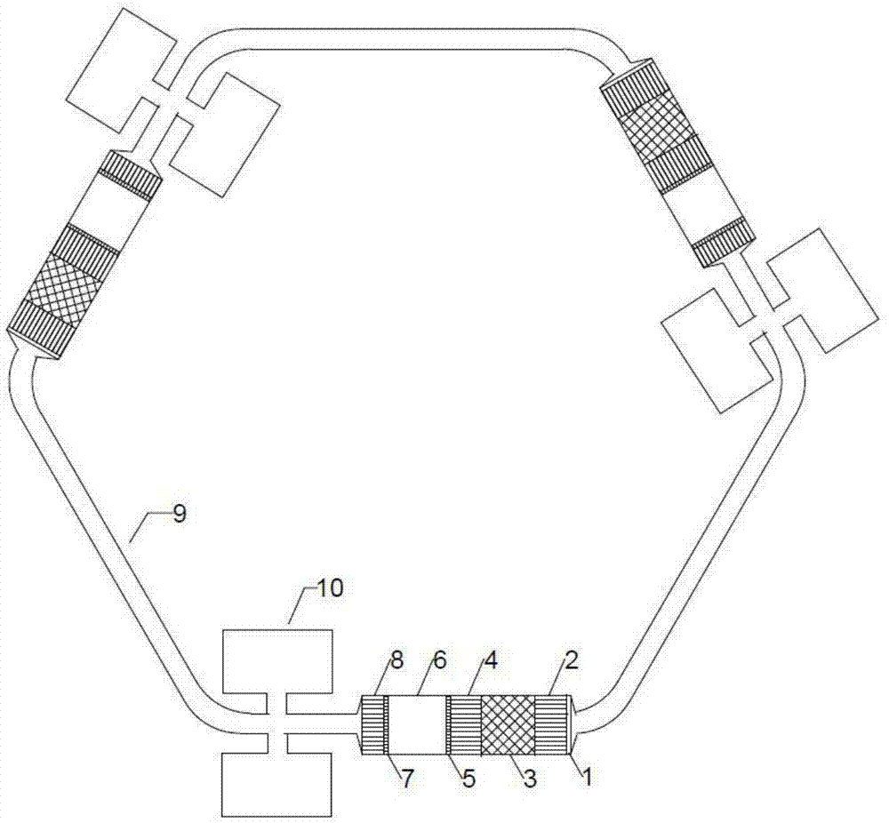
[0027] Figure 4 It is a structural schematic diagram of a traveling wave thermoacoustic engine driven linear motor system (embodiment 2) with multi-stage amplification of sound power of the present invention; Figure 4 As shown, the multistage sound power amplification traveling wave thermoacoustic engine system of the present embodiment 2 is composed of 4 stages (#1 thermoacoustic engine unit, #2 thermoacoustic engine unit, #3 thermoacoustic engine unit and #4 thermoacoustic engine unit Thermoacoustic engine units with equal length and unequal cross-sectional area and load 10 are composed; thermoacoustic engine units at all levels are connected end-to-end through resonant tubes 9 with equal length and unequal cross-sectional area to form a loop structure; each stage of thermoacoustic engine The unit is composed of DC suppressor 1, main cooler 2, regenerator 3, heater 4, high temperature end laminar fluidization element 5, thermal buffer pipe 6, room temperature end laminar f...


PUM


Abstract

The invention discloses an acoustic power multi-stage amplification traveling-wave thermoacoustic engine system, which consists of a loop structure formed by connecting N stages of thermoacoustic engine units end to end through resonant tubes and a load, wherein each unit is equal in length and unequal in cross sectional area; the units form a loop from large to small cross sectional areas or from small to large cross sectional areas, and the stages of the units are higher if the cross sectional areas of the units are larger; the resonant tubes are equal in length and unequal in cross sectional area; the cross sectional area of the resonant tube between the first and Nth stages of units is minimal, and the cross sectional areas of the other resonant tubes are enlarged along with the enlargement of the cross sectional areas of the units connected by the resonant tubes. When the system works, heat is converted into acoustic power under the temperature gradient of a reheater of each unit, the acoustic power is transmitted and amplified along the forward direction of the temperature gradient, and the amplified acoustic power is transmitted into the reheater of the unit of the next stage, and is amplified and transmitted to the unit of the stage after the next stage; most of the acoustic power which is amplified in multiple stages is consumed by the load, and the other is transmitted to the first stage of unit to continue the process. According to the system, an acoustic power index can be multiplied, so that a high-power load is favorably driven; the reheaters are positioned in a traveling-wave phase, so that thermoacoustic conversion efficiency is high.

Description

technical field [0001] The invention belongs to the field of engines, in particular to a traveling wave thermoacoustic engine system with multi-stage amplification of sound power. Background technique [0002] A thermoacoustic engine is a device that uses pipes and heat exchangers to obtain a suitable sound field inside it, and converts heat energy into sound energy through the interaction between the working medium and the regenerator. It has no mechanical moving parts and high reliability , Long life and other advantages. According to the sound field characteristics of thermoacoustic conversion, thermoacoustic engines are divided into traveling wave thermoacoustic engines and standing wave thermoacoustic engines. The traveling wave thermoacoustic engine is based on the reversible thermoacoustic Stirling cycle, which has potential high efficiency compared with the standing wave thermoacoustic engine based on the irreversible cycle, and is an important direction of research...

Claims


Application Information

Patent Timeline
Patent Type & Authority Applications(China)
IPC IPC(8): F02G1/043
CPCF02G1/043
Inventor 罗二仓徐静远胡剑英戴巍吴张华张丽敏余国瑶王晓涛陈燕燕
Owner TECHNICAL INST OF PHYSICS & CHEMISTRY - CHINESE ACAD OF SCI
Learn More