
Sealed cooling tower

A cooling tower, closed technology, applied in the field of sealed cooling towers, can solve the problems of poor light and thermal stability of polyvinyl chloride, damage to equipment structure and performance, uneven quality, etc., to achieve safe and reliable operation and improve cooling efficiency , the effect of small footprint

Inactive Publication Date: 2015-07-15
济南秦泰热工技术有限公司
View PDF5 Cites 7 Cited by
  • Summary
  • Abstract
  • Description
  • Claims
  • Application Information

AI Technical Summary

Problems solved by technology

[0004] The closed cooling tower needs to use polyvinyl chloride filler to promote the cooling of the external circulating water. The light and thermal stability of polyvinyl chloride is poor, and it is prone to aging after long-term use, which will cause certain damage to the structure and performance of the equipment. influences
Moreover, substances that pollute the environment will be produced during the production and manufacture of polyvinyl chloride fillers from raw materials to finished products, which is not environmentally friendly
Moreover, the quality of polyvinyl chloride fillers currently on the market is uneven, some of which do not meet the national standards and are not flame retardant products, but are still used in cooling tower equipment, causing fire hazards
[0005] Due to the limitation of the structure of the existing closed cooling tower, it is necessary to meet the use and installation requirements of polyvinyl chloride filling materials and heat exchange coils. reduced volume
[0006] In addition, the current closed cooling towers are basically shells made of glass fiber reinforced plastics, which have a series of shortcomings and need to be improved.

Method used


Image

  • Sealed cooling tower
  • Sealed cooling tower
  • Sealed cooling tower

Examples


Embodiment Construction

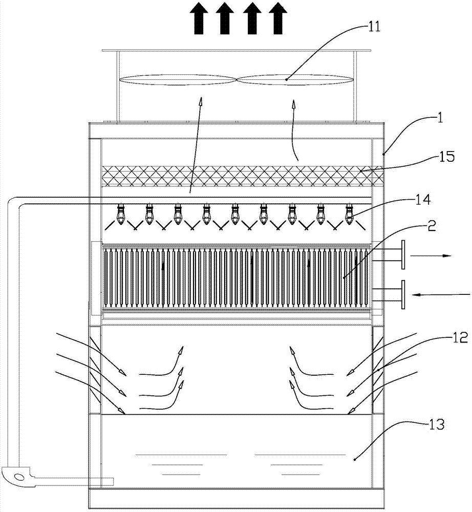
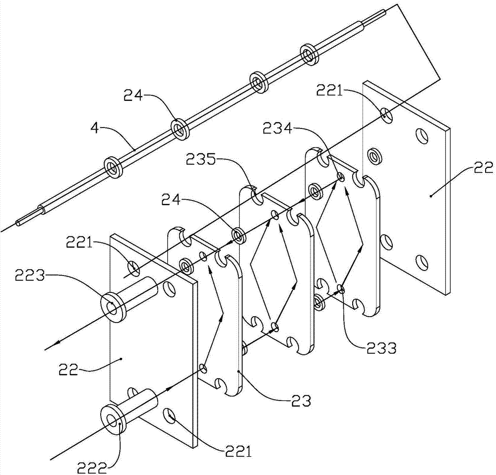
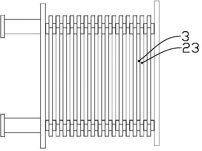
[0036] Such as Figure 1 to Figure 7 as shown,

[0037] A key point and protection point of the present invention is a plate-type closed cooling tower with an outer shell of galvanized steel plate, in which the outer guard plate, top plate, bottom plate and air outlet of the cooling tower are made of galvanized steel plate with high corrosion resistance , The corrosion resistance of galvanized steel sheet is 6-8 times that of ordinary galvanized steel sheet, and it can still maintain its original appearance in harsh environments. At the same time, it has a unique self-healing and anti-corrosion performance of the cut surface coating, stable processing performance, excellent wear resistance and scratch resistance, beautiful appearance and long service life. This type of cooling tower has the characteristics of beautiful appearance, flexible combination, high efficiency and low consumption, environmental protection and energy saving, easy maintenance, firm structure and long se...


PUM


Abstract

The invention discloses a sealed cooling tower and solves the problems that an existing cooling tower is filled with polyvinyl chloride packing and the heat exchange efficiency is low. The sealed tower comprises a tower body, a spraying system, a heat exchange part and a fan, wherein the heat exchange part is a cooler; multiple shell type heat exchange units are vertically arranged in the cooler at intervals; a spraying and air flow channel is formed between the outer walls of two adjacent heat exchange units; at least one inlet and at least one outlet are formed in each heat exchange unit; at least one set of to-be-cooled medium channel penetrating through the inlet and the outlet of each heat exchange unit is formed in the heat exchange unit; the inlets of the heat exchange units are communicated with one another and are converged to form a to-be-cooled liquid medium inlet; the outlets of the heat exchange units are communicated with one another and are converged to form a to-be-cooled liquid medium outlet. The inside structure of the sealed cooling tower is simplified and the cooling efficiency is improved.

Description

technical field [0001] The invention relates to the field of sealed cooling towers, in particular to a sealed cooling tower with a plate structure. Background technique [0002] The closed cooling tower is a kind of high-efficiency cooling equipment. It mainly uses the evaporation latent heat of water to remove the heat of the process fluid, completes the cooling of the process fluid, and realizes the recycling of cooling water. It has been widely used in refrigeration, chemical industry , food, injection molding, metallurgy, textile and other industries. [0003] Existing closed cooling towers usually adopt a cooling method combining polyvinyl chloride filling material and heat exchange coil, that is, the process circulating fluid flows in the heat exchange coil while the external circulating water flows through the polyvinyl chloride filling material to cool down. The water in contact with the heat exchange coil transfers heat to cool the water in the coil. [0004] The ...

Claims


Application Information

Patent Timeline
Patent Type & Authority Applications(China)
IPC IPC(8): F28C1/00F28F25/00
Inventor 张永庆
Owner 济南秦泰热工技术有限公司
Learn More