
A Spin-Hall Effect-Assisted Spin-Transfer Torque Nonvolatile Flip-Flop

A technology of spin Hall effect and spin transfer torque, which is applied in the direction of instruments, static memory, digital memory information, etc., and can solve problems such as large resistance, long write delay, STT-MTJ error flip, etc.

Active Publication Date: 2017-04-26
BEIHANG UNIV
View PDF4 Cites 0 Cited by
  • Summary
  • Abstract
  • Description
  • Claims
  • Application Information

AI Technical Summary

Problems solved by technology

[0004] (1) During the write operation of STT-MTJ, the write current needs to flow through the entire device. Since the resistance of the device itself is relatively large, the write power consumption of STT-MTJ is relatively large
[0005] (2) The read and write operations of STT-MTJ use the same branch. In order to avoid the breakdown of the oxide layer of STT-MTJ, the write current must be limited to a small value, which leads to a longer write time. Delay
[0006] (3) In the read operation, although the read current is usually smaller than the write current, it is still possible to cause an error flip to the state of the STT-MTJ, resulting in read disturbance

Method used


Image

  • A Spin-Hall Effect-Assisted Spin-Transfer Torque Nonvolatile Flip-Flop
  • A Spin-Hall Effect-Assisted Spin-Transfer Torque Nonvolatile Flip-Flop
  • A Spin-Hall Effect-Assisted Spin-Transfer Torque Nonvolatile Flip-Flop

Examples


Embodiment Construction

[0052] The invention provides a non-volatile trigger of spin transfer torque assisted by spin Hall effect. The substantive features of the present invention are further described with reference to the accompanying drawings. The drawings are all schematic diagrams, and the parameters such as the thickness, area and volume of each functional layer or region involved are not actual dimensions. Detailed exemplary embodiments are disclosed herein, specific structural and functional details of which are merely for the purpose of describing particular embodiments, therefore, the invention may be embodied in many alternative forms and should not be construed as It is intended to be limited only to the exemplary embodiments set forth herein, but to cover all changes, equivalents, and alternatives falling within the scope of the invention. Additionally, well-known elements, devices and subcircuits of the invention will not be described in detail or will be omitted so as not to obscure ...


PUM


Abstract

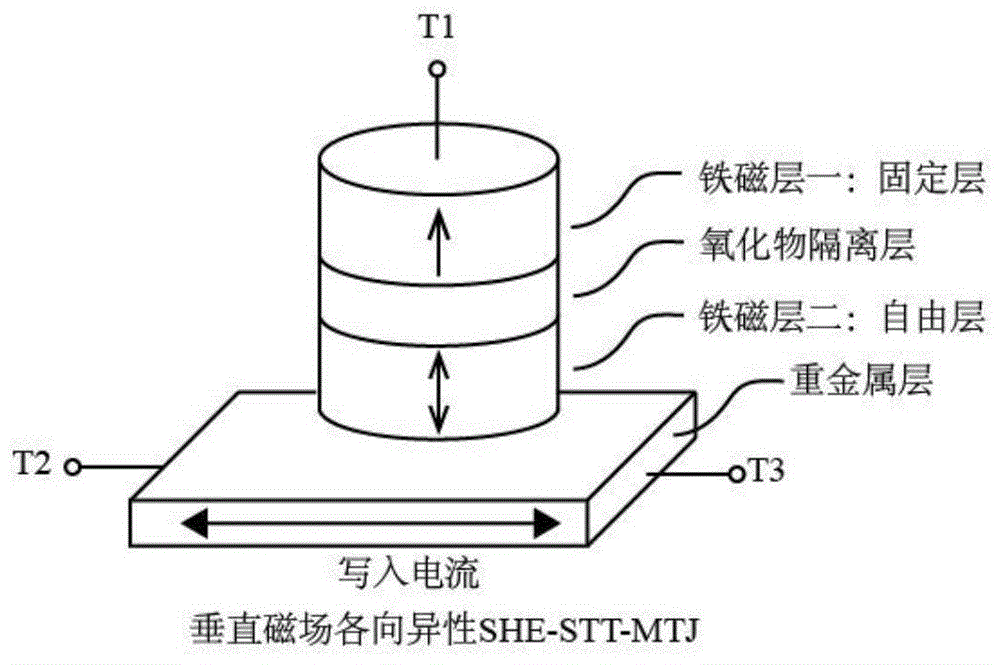
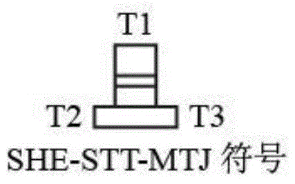
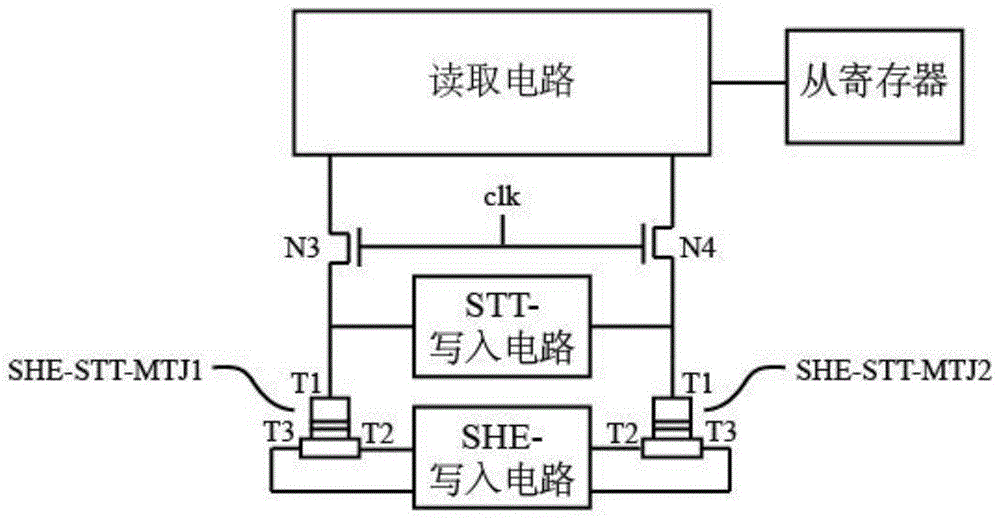
The invention relates to a spin-hall-effect-assisted spin-transfer torque nonvolatile trigger which is composed of a pair of spin-hall-effect-assisted spin-transfer torque magnetic tunnel junctions, namely SHE-STT-MTJ1 and SHE-STT-MTJ2, a pair of NMOS transistors, namely N3 and N4, an STT-writing circuit, an SHE-writing circuit, a reading circuit and a slave register, wherein the T1 ends of the SHE-STT-MTJ1 and the SHE-STT-MTJ2 are connected with the STT-writing circuit, the T2 and T3 ends of the SHE-STT-MTJ1 and the T2 and T3 ends of the SHE-STT-MTJ2 are connected with the SHE-writing circuit, the T1 ends of the SHE-STT-MTJ1 and the SHE-STT-MTJ2 are respectively connected with the source electrodes of the N3 and N4 transistors, and the gate electrodes of the two NMOS transistors are directly interconnected and are controlled by a clk clock signal. The spin-hall-effect-assisted spin-transfer torque nonvolatile trigger provided by the invention has the characteristics of being low in consumption and high in speed and being reliable.

Description

technical field [0001] The invention relates to a spin-transfer torque non-volatile trigger assisted by spin Hall effect. It belongs to the field of microelectronic devices. Background technique [0002] In digital logic circuits, flip-flops (Flip-Flop) play a vital role. However, with the shrinking of process nodes, the leakage current caused by the quantum tunneling effect continues to increase, and electronic circuits based on traditional complementary metal-oxide-semiconductor (CMOS) transistors face the dual challenges of power consumption and reliability, making it difficult to meet the challenges of modern integration. circuit needs. Therefore, it is necessary to design a new type of flip-flop to solve these problems in order to continue the development of Moore's Law. [0003] In recent years, flip-flops based on some new types of non-volatile components have been emerging. Among them, the magnetic non-volatile flip-flop based on the spin transfer torque (Spin Tr...

Claims


Application Information

Patent Timeline
Patent Type & Authority Patents(China)
IPC IPC(8): G11C11/16
CPCG11C11/161G11C11/1675G11C11/1693G11C11/18
Inventor 郑晨天康旺郭玮赵巍胜张有光
Owner BEIHANG UNIV
Learn More