
Processing method of combined high-speed electromagnet core

A technology of high-speed electromagnet and processing method, which is applied in the direction of electromagnet with armature, inductance/transformer/magnet manufacturing, electromagnet, etc. Low processing cost, high processing efficiency, convenient and smooth perfusion

Active Publication Date: 2017-03-01
零八一电子集团四川力源电子有限公司
View PDF5 Cites 0 Cited by
  • Summary
  • Abstract
  • Description
  • Claims
  • Application Information

AI Technical Summary

Problems solved by technology

The disadvantage of this kind of structural product is that the structure is more complicated. The annular coil groove can only be processed after the three parts are connected (bonded or welded). The connection structure is poor in firmness, and the bonding or welding structure is easily damaged during processing. Low efficiency and high defective rate

Method used


Image

  • Processing method of combined high-speed electromagnet core
  • Processing method of combined high-speed electromagnet core
  • Processing method of combined high-speed electromagnet core

Examples


Embodiment 1

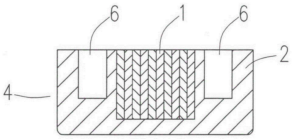
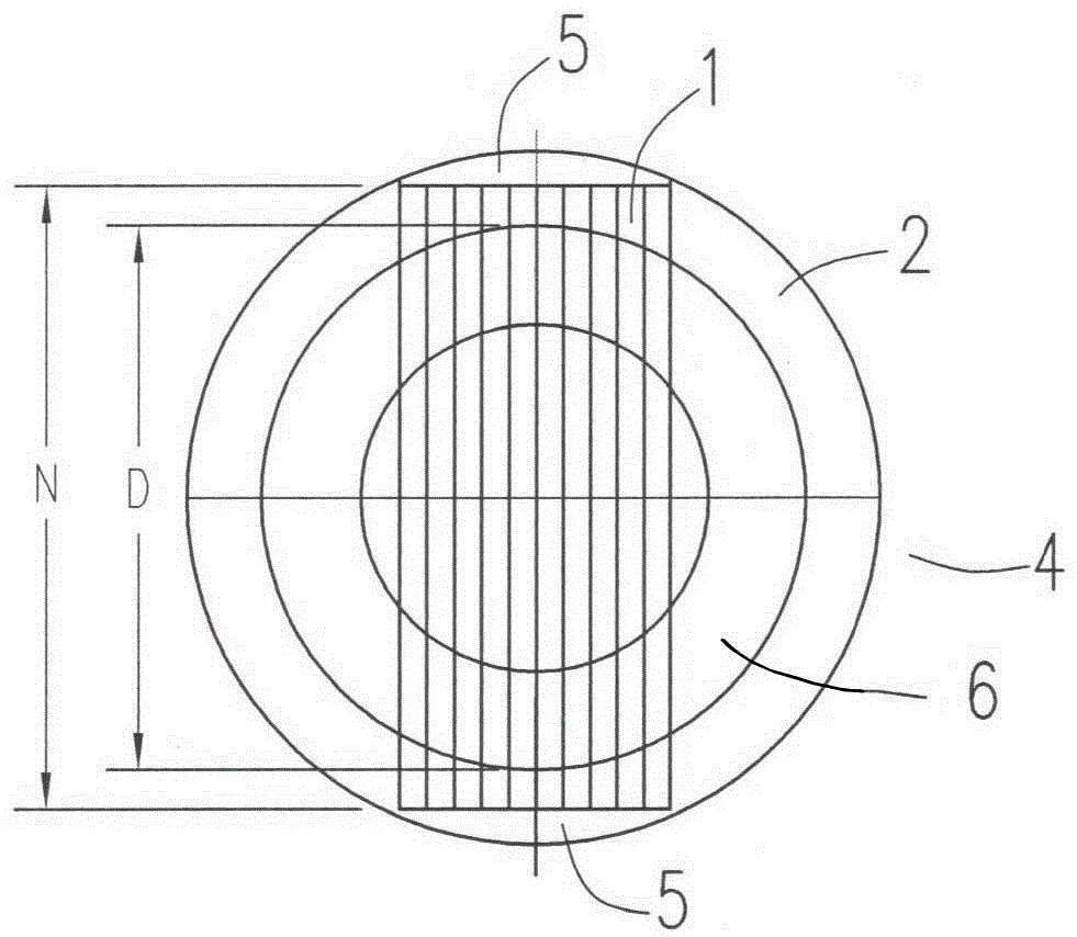
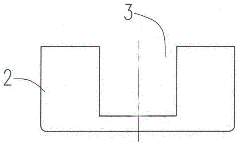
[0026] A processing method for a combined high-speed electromagnet core is characterized in that it comprises the following steps: (see Figure 1 to Figure 8 )

[0027] a, a conventional method is processed to form a cylindrical iron core seat 2 with a radial through groove 3;

[0028] b, cutting the silicon steel strip with a thickness of 0.2mm into a rectangular silicon steel sheet 1 with the same length and width, the length M of the silicon steel sheet 1, the length N of the radial through groove 3, and the outer diameter D of the annular coil groove 6 satisfy the following Relational formula: D

[0029] c. Embed several pieces of rectangular silicon steel sheets 1 into the radial through grooves 3 of the iron core seat 2, plug them tightly, and assemble them into a blank of the iron core assembly 4 with a pair of notches 5 on both sides;

[0030] d. The blank is welded by argon arc welding at a pair of gaps 5. After the welding is completed, several silicon steel s...

Embodiment 2

[0033] A processing method for a combined high-speed electromagnet core is characterized in that it comprises the following steps:

[0034] a. A cylindrical iron core seat with a radial through groove is processed by the conventional method;

[0035] b. Cut the 0.5mm thickness silicon steel strip into rectangular silicon steel sheets with the same length and width. The length M of the silicon steel sheet, the length N of the radial through groove, and the outer diameter D of the annular coil groove satisfy the following relationship: D Figure 9 );

[0036] c. Embed several pieces of rectangular silicon steel sheets into the radial through grooves of the iron core seat, plug them tightly, and assemble them into a blank of an iron core assembly with a pair of notches on both sides;

[0037] d. The blank is welded by argon arc welding at a pair of gaps. After the welding is completed, several silicon steel sheets are connected with the core seat to form a core assembly;

[003...


PUM


Abstract

The invention provides a processing method of a novel combined high-speed electromagnet iron core. The novel combined high-speed electromagnet iron core consists of a plurality of silicon steel sheets and an iron core seat, and is characterized by comprising the following steps that a, the iron core seat is processed by a conventional method; b, rectangular silicon steel sheets are cut; c, the rectangular silicon steel sheets are embedded into an iron core combining element blank element of the iron core seat, and the iron core combining element blank element is provided with a pair of notches; d, the blank element is welded at the notch part through argon arc welding; e, an annular coil groove is cut and processed in the end surface. The processing method has the advantages that the structure is simple, the processing process is simple, the production efficiency is high, the processing cost is low, in the electromagnet assembly process in the subsequent work procedure, when the iron core combining element is assembled and bonded with a case, the notches naturally formed at the two sides form an epoxy glue filling opening, the filling is convenient and smooth, and the glue filling quality is guaranteed.

Description

technical field [0001] The invention relates to a processing method for an electromagnet structure, in particular to a processing method for a combined iron core structure of a high-speed electromagnet. Background technique [0002] High-speed electromagnets are key control actuators for control systems such as electronically controlled fuel injection systems for diesel engines. In the diesel engine electronically controlled fuel injection system, its function is to execute the system ECU command, control the pump valve to close, and complete the precise fuel injection. The electromagnet is required to have the characteristics of fast response speed, low eddy current loss, large electromagnetic attraction force, and small size. [0003] The Chinese utility model patent No. 20082063803.1 discloses a combined high-speed electromagnet iron core, which includes silicon steel laminates, a circular iron core seat, and a non-magnetic metal jacket. Assembled body, an annular coil ...

Claims


Application Information

Patent Timeline
Patent Type & Authority Patents(China)
IPC IPC(8): H01F41/02H01F3/02H01F7/08
Inventor 黄健陈继锦
Owner 零八一电子集团四川力源电子有限公司
Learn More