

Ground microgravity dynamic loading simulation mechanism for satellite
A dynamic loading, microgravity technology, applied in the simulation devices of space navigation conditions, space navigation equipment, transportation and packaging, etc., can solve the problems of simulation simulation experiment distortion and other problems, reduce the position and attitude following error, the simulation is complete and realistic, Pose-following for precise effects
- Summary
- Abstract
- Description
- Claims
- Application Information
AI Technical Summary
Problems solved by technology
Method used
Image

Examples
Embodiment Construction
[0028] The invention will be described in further detail below in conjunction with the accompanying drawings.
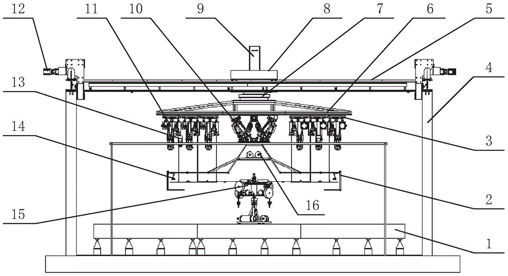
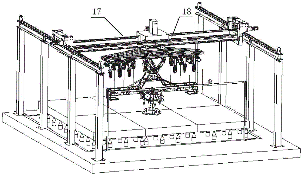
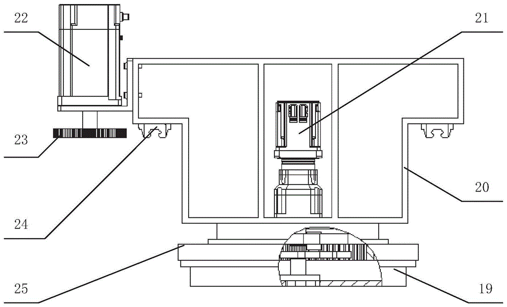
[0029] Such as figure 1 , figure 2As shown, the present invention includes a marble platform 1, a five-degree-of-freedom air-floating platform 15, a three-degree-of-freedom crane 8, a truss 6, a two-dimensional servo platform 3, a Stewart platform 10, a constant force suspension mechanism 11, a solar wing following the truss 2, Loading manipulator 14, pose recognition mechanism and control system 9, wherein a three-degree-of-freedom crane 8 is arranged above the marble platform 1, a truss 6 is provided below the three-degree-of-freedom crane 8, and two A three-dimensional servo platform 3 and a Stewart platform 10, the solar wing following truss 2 is installed under the Stewart platform 10, the loading manipulator 14 is installed on the solar wing following truss 2, and a five-degree-of-freedom air compressor is placed on the marble platform 1. The floating platfo...
PUM
 Abstract
Description
Claims
Application Information